I meant to post this information 10 years ago…better late than never, I guess.
The UCA202 is not state of the art by any means, but small, light, rugged, no fiddly knobs to adjust or get noisy, and cheap…works great for non-critical travel measurement system. However, as many have noticed, if you try to use it for impedance measurements using the built in headphone amp and a 47 – 100 ohm reference resistance you will notice an issue with rising impedance error at low frequencies. I traced the problem to an unregulated voltage reference that is shared by all op amps. The op amps are powered directly from the USB +5V rather than a split +/- Supply. The voltage reference is needed to position the audio signal between ground and +5V.
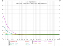
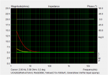
Attachment #1: A trend plot of measured impedance for a 5 ohm resistor for a range of reference resistor values used with a power amp to illustrate the issue.
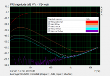
Attachment #2: Here is an overlay plot showing the cross-talk vs the loop-back measurement.
- red curve is the loop back measurement
- orange curve is stock unit with inputs shorted
- grey and blued curves are with inputs shorted but bigger filter cap for reference voltage
- purple curve is when input op amp reference is switched to using the regulated Vref in the PCM2902
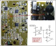
Attachment #3: One option for improvement is to increase the size of the capacitor (C13) used to filter/stabilize the reference voltage . The board has room for a 1000uF. This is a simple option that provides about 20dB improvement.
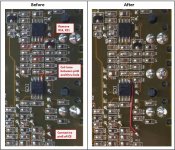
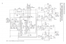
Attachment #4: A better option, if your soldering skills are up for it, is to use a separate reference voltage source for the input op amp. Rather than adding circuitry, I found from the TI datasheet that pin 14 on the PCM2902 provides a regulated reference voltage for the internal DAC/ADC buffers. Furthermore, the TI demo board schematic shows this voltage being used as reference voltage for external op amp buffers as well.
- remove R14 & R21 (required because of direct coupling in the monitor signal path, the monitor switch will no longer work)
- cut trace between pin 5 of IC5 and the thru hole (this is the shared voltage reference trace)
- add connection from pin 5 of IC5 to pin 14 of PCM2902 (conveniently available at C1)
Attachment #5: A comparison of improvements from the two different fix options with 47 ohm reference resistor.
Attachments #6,7: Excerpts from TI documentation
The UCA202 is not state of the art by any means, but small, light, rugged, no fiddly knobs to adjust or get noisy, and cheap…works great for non-critical travel measurement system. However, as many have noticed, if you try to use it for impedance measurements using the built in headphone amp and a 47 – 100 ohm reference resistance you will notice an issue with rising impedance error at low frequencies. I traced the problem to an unregulated voltage reference that is shared by all op amps. The op amps are powered directly from the USB +5V rather than a split +/- Supply. The voltage reference is needed to position the audio signal between ground and +5V.
Attachment #1: A trend plot of measured impedance for a 5 ohm resistor for a range of reference resistor values used with a power amp to illustrate the issue.
Attachment #2: Here is an overlay plot showing the cross-talk vs the loop-back measurement.
- red curve is the loop back measurement
- orange curve is stock unit with inputs shorted
- grey and blued curves are with inputs shorted but bigger filter cap for reference voltage
- purple curve is when input op amp reference is switched to using the regulated Vref in the PCM2902
Attachment #3: One option for improvement is to increase the size of the capacitor (C13) used to filter/stabilize the reference voltage . The board has room for a 1000uF. This is a simple option that provides about 20dB improvement.
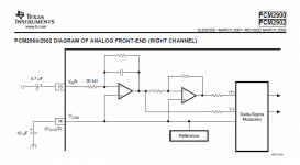
Attachment #4: A better option, if your soldering skills are up for it, is to use a separate reference voltage source for the input op amp. Rather than adding circuitry, I found from the TI datasheet that pin 14 on the PCM2902 provides a regulated reference voltage for the internal DAC/ADC buffers. Furthermore, the TI demo board schematic shows this voltage being used as reference voltage for external op amp buffers as well.
- remove R14 & R21 (required because of direct coupling in the monitor signal path, the monitor switch will no longer work)
- cut trace between pin 5 of IC5 and the thru hole (this is the shared voltage reference trace)
- add connection from pin 5 of IC5 to pin 14 of PCM2902 (conveniently available at C1)
Attachment #5: A comparison of improvements from the two different fix options with 47 ohm reference resistor.
Attachments #6,7: Excerpts from TI documentation
Attachments
-
 UCA202_Z_Rsense_Trend.png46.5 KB · Views: 815
 -
 UCA202_Crosstalk_trends.png43.2 KB · Views: 906
 -
 UCA202_Fix_01.jpg108.1 KB · Views: 993
 -
 UCA202_Fix_02.jpg114.7 KB · Views: 1,156
 -
 TI_PCM2902_DemoBoard.png108.4 KB · Views: 979
 -
 TI_PCM2902_Internal_Vref.png28.1 KB · Views: 802
 -
 UCA202_Fix_trends.png18.3 KB · Views: 853
Last edited:
Applying both fixes would reduce the LF crosstalk between the Left and Right outputs at low frequencies. This might be beneficial on paper, but probably not in the real world for listening to music where channel separation requirements at LF is not general an issue. If you are just using the UCA202 for a measurement system, I can’t think if any benefit since measurements systems output the same signal to both channels. No harm in it though. Another option I never investigated was to see if crosstalk remained low if the PCM2902 voltage reference was used for all the op amps like shown in the schematic of the TI demo board.Is there any benefit from applying both fixes?
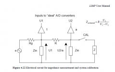
Refer to the attached impedance measurement setup. The output impedance of the source (Rg) does not affect results for a 2-probe impedance measurement setup. The issue is that crosstalk is sending a portion of the signal source(e) directly to the inputs (U1), (U2) bypassing the source and reference resistances (Rg) and (R). Since input (U2) will always be lower in magnitude than (U1) it becomes proportionally more and more contaminated at low frequencies from crosstalk with increasing reference resistor value (R). This is what Attachment #1 was illustrating.Your OUTPUT Z is not low. The amplifier output is jack is driven by 100 ohms and 10uf, so the #1 graph is not a surprise to me. 100 Ohms & 10uf = 150 Hz
You can see in Attachment #5 of the original post(green curve), that once the crosstalk is removed the resistance is properly measured at low frequency even with high output impedance.
BTW, just to clarify, the schematic posted was for the TI demo board for the PCM2902, not the Behringer UCA202. I do not have the schematic for the UCA202, but circuit board tracing shows the output impedance of the UCA202 headphone op amp to be 47ohm + 100uF.
Attachments
Last edited:
Interesting! I've been playing with this sound card sometime ago. I realized the problem with I/O buffers so I bypassed them completely and used the buffers of Pete Millett's interface connected directly on the audio codec chip. This cured the low frequency problem but did nothing at all to another problem I faced that doesn't seem to be present in your case. That was an ugly phase shift at the higher frequencies, not annoying with THD measurements but terrible for impedance measurements. I noticed you are are talking about TI PCM2902. Mine has a "cool audio V2902" It seem all the same but is it?
It seem all the same but is it?I’m not sure if the V2902 is identical to the PCM2902 or not. Behringer acquired Cool Audio some time ago, and I would guess that they are manufacturing their own copy of the PCM2902 thru a licensing agreement with TI.
Regarding the phase shift at high frequencies: This results from the 1 sample timing difference between the inputs of the PCM2902. (see attached Errata sheet Section 2.2) As you saw in my measurements, Calibration in ARTA (or REW) takes care of the resulting phase shift. I just noticed recently that REW even identifies the 1 sample timing difference in a pop-up window during calibration.
Regarding the phase shift at high frequencies: This results from the 1 sample timing difference between the inputs of the PCM2902. (see attached Errata sheet Section 2.2) As you saw in my measurements, Calibration in ARTA (or REW) takes care of the resulting phase shift. I just noticed recently that REW even identifies the 1 sample timing difference in a pop-up window during calibration.
Attachments
Hi sir! Your words are not too old for me  Since I have a couple of pcm2900 lying around I was interested in building something that would resemble a uca202, so I can record myself on a pc. Can you help me understanding which kind of input should I add to the standard ADC circuitry? I'm thinking in a unity gain inverting stage around a 4558, which would be run in single supply.
Can you help me?
Since I have a couple of pcm2900 lying around I was interested in building something that would resemble a uca202, so I can record myself on a pc. Can you help me understanding which kind of input should I add to the standard ADC circuitry? I'm thinking in a unity gain inverting stage around a 4558, which would be run in single supply. Can you help me?
Hi,
Datasheet app notes provide schematics also attached in the first post of this thread. For starters you could simply connect audio source to pins #12,13 via coupling capacitors. PCM2900 has internal digital antialiasing filter. If you need to add opamp buffers, then pin #8 to 5V (could be usb Vbus) pin#4 to ground and pin #3 and #5 respectively to Vcom ( PCM2900 pin#14) Datasheet schematic also shows additional antialiasing filter on the feedback loop of the input opamps. Although this should be tuned for the particular opamp used, generally it should work roughly for other opamps. Or simply omitted and build a straightforward inverting stage.
Datasheet app notes provide schematics also attached in the first post of this thread. For starters you could simply connect audio source to pins #12,13 via coupling capacitors. PCM2900 has internal digital antialiasing filter. If you need to add opamp buffers, then pin #8 to 5V (could be usb Vbus) pin#4 to ground and pin #3 and #5 respectively to Vcom ( PCM2900 pin#14) Datasheet schematic also shows additional antialiasing filter on the feedback loop of the input opamps. Although this should be tuned for the particular opamp used, generally it should work roughly for other opamps. Or simply omitted and build a straightforward inverting stage.
Hi!
Thank you for your reply. As I'll be connecting a guitar to the PCM, I was thinking in adding a buffer to handle the pickup impedance. I don't have the OPA2353 available where I live but since this card uses 4558's I was thinking in using those. I'm not sure that I would need some gain for the opamp stage. I don't have much room to do that anyway bc I want to power the entire thing from USB 5v
Sebas
I think the 4558 is a bad choice if you want it to operate on 5V.
The 4558 (datasheet) is intended for higher voltage supplies. It is explicitly not rail to rail. Since its inputs and outputs have to stay a couple of volts from the supply rails, you won't have much working space for your signals - if it'll work at all on just 5V.
The 4558 (datasheet) is intended for higher voltage supplies. It is explicitly not rail to rail. Since its inputs and outputs have to stay a couple of volts from the supply rails, you won't have much working space for your signals - if it'll work at all on just 5V.
My interpretation is that 4558 could work at a min of 5V single supply and output a couple of volts less. PCM2900 analog input needs 0,6*5Vvcccl=3Vp-p. So it might work with some distortion but since it's for a guitar... 4558 input "resistanse" is 5M according datasheet. How much of this can you afford to drop to match a guitar pickup? Inverting topology doesn't seem suitable for that.
The UCA202 did use the 4558 in early production, but it was just for the headphone amp.
Later production changed headphone amp to the 4556A.
The line input/output buffers have always been 2740, which are specifically designed for low voltage operation.
Later production changed headphone amp to the 4556A.
The line input/output buffers have always been 2740, which are specifically designed for low voltage operation.
Attachments
Ahh I see! Since the shipping cost of getting some to build would be more than of the UCA202 itself I think I will just use a normal 9V supply and get a common opamp to do the job. Besides that I've got another question: MagicBus said that the PCM needs 0,6*5Vvcccl=3Vp-p. Is that the max voltage it can handle?
Sorry if my questions seem a bit dumb, I'm a diyer with no formal knowledge on electronics trying to learn
Sebas
Sorry if my questions seem a bit dumb, I'm a diyer with no formal knowledge on electronics trying to learn
Sebas
> electronics trying to learn
So read the Data Sheet.
PCM2900 - Google Search
https://www.ti.com/lit/ds/symlink/pcm2900.pdf
page 4
So read the Data Sheet.
PCM2900 - Google Search
https://www.ti.com/lit/ds/symlink/pcm2900.pdf
page 4
My interpretation is that 4558 could work at a min of 5V single supply and output a couple of volts less.
Nope, it needs an absolute minimum of 10V (aka +/-5V). For 5V operation there are now a plethora of rail-to-rail opamps good for the task. The MCP6022 will see you fine I suspect. My fave is the AD8656 as it can drive headphones directly if needed.
- Home
- Design & Build
- Equipment & Tools
- Behringer UCA202: Fixing the Low Frequency Cross-talk