Project page on Github
A simple, high-quality DIY microphone pre-amplifier with switched gain.
The background for this project was that I needed a simple but good microphone preamp for doing acoustic measurements. I needed a switched gain to be able to reproduce the gain setting in a more predictable way than what is possible with a potmeter. I could not find any existing DIY designs, so I decided to make one.
The design is based on the excellent THAT1510 preamp IC. It is also compatible with SSM2019 or INA217. I have followed all THAT's datasheets and app-notes to implement a robust, best-practice design.
A goal was to use simple through-hole parts that I and other DIYers usually have in our parts drawer. So there are no additional IC's or voltage regulators for example, it just uses simple transistors, capacitors and zener diodes for supply filtering and regulation. I selected affordable switches and connectors to keep cost down. Many parts can be substituted without sacrificing performance.
This is an open-source project released under CC-BY-SA-4.0 license. It basically means you can use it as you want as long as you share modifications under the same license, and attribute back to this project. See LICENSE.txt for details.
Specifications
-----
* PCB dimensions 75mm x 120mm, fits the Hammond 1455K120x(1455K1201 - Hammond Mfg.) enclosure.
* Gain switch on top of enclosure for easy access.
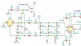
Schematic
-----

Desktop version:
-----

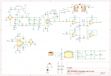
Rack version:
-----


Measurements
-----
### Output noise vs gain
20-22kHz BW un-wtd, 150ohm source impedance
| Gain(dB) | Output Noise (dBu) | EIN (dBu) |
| --- | --- | --- |
| 0 | -98.5 | -98.5 |
| 10 | -98.2 | -108.2 |
| 15 | -97.8 | -112.8 |
| 20 | -96.8 | -116.8 |
| 25 | -95.6 | -120.6 |
| 30 | -93.2 | -123.2 |
| 35 | -89.8 | -124.8 |
| 40 | -86.8 | -126.8 |
| 45 | -82.6 | -127.6 |
| 50 | -77.8 | -127.8 |
| 55 | -73.1 | -128.1 |
| 60 | -68.3 | -128.3 |
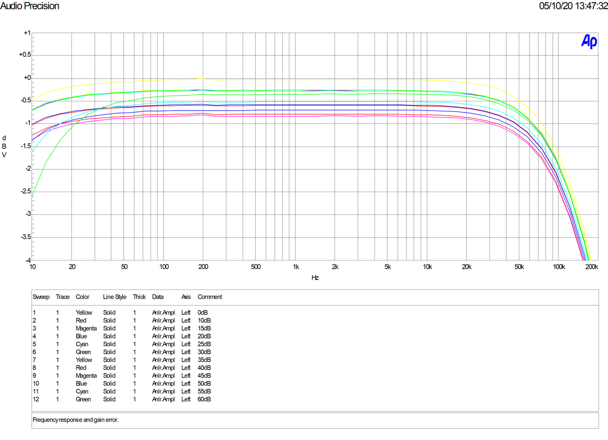
### Frequency Response
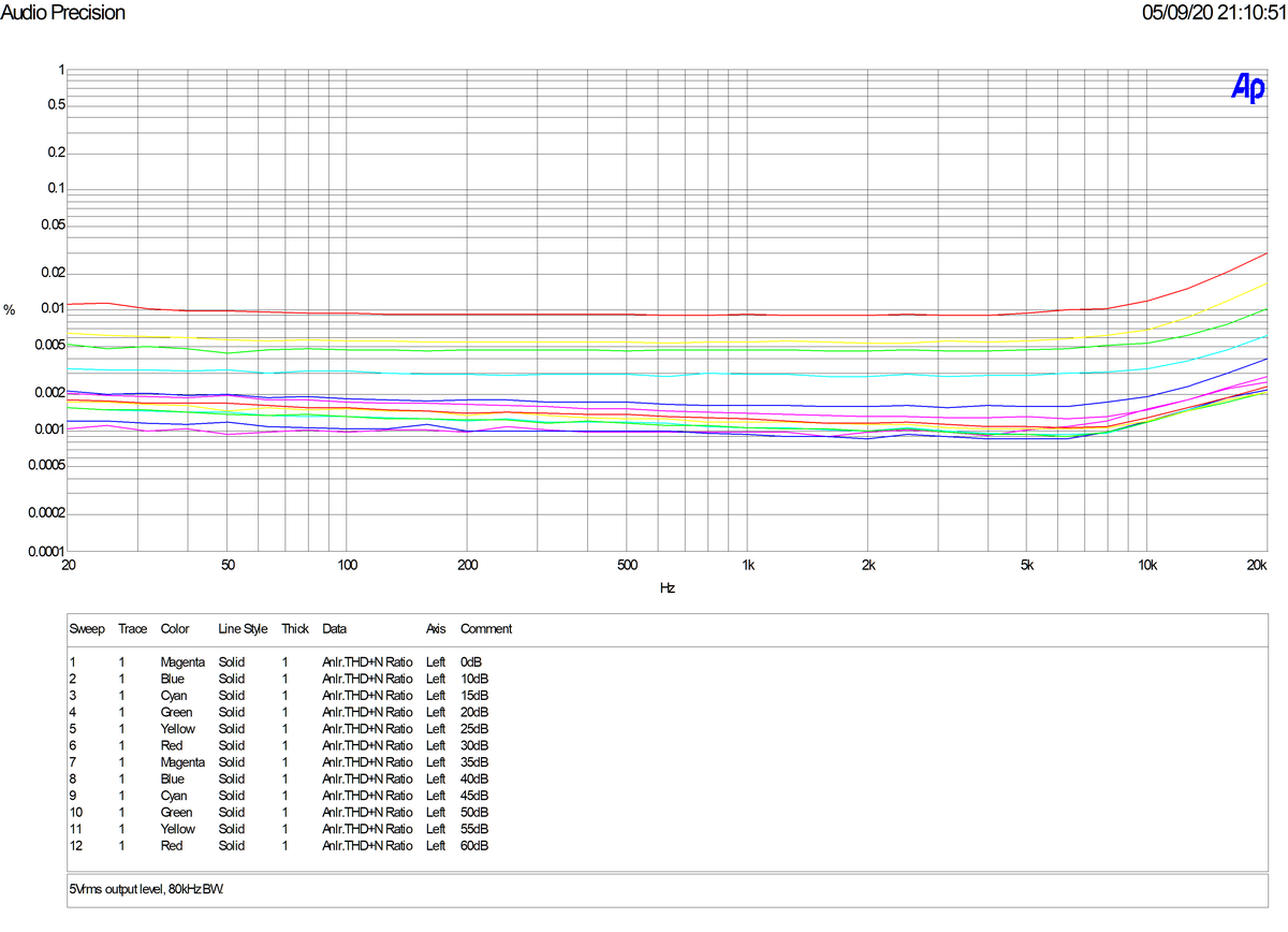
### THD+N vs Frequency
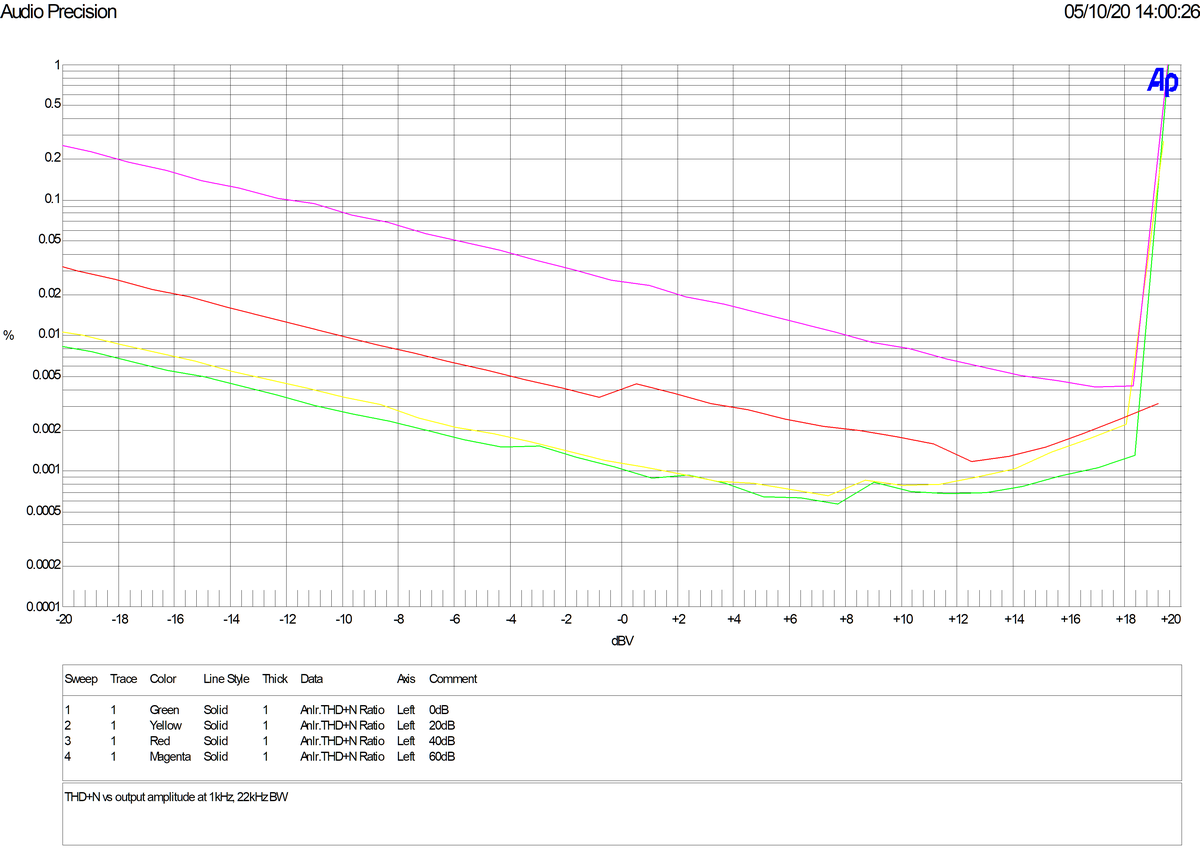
### THD+N vs Amplitude
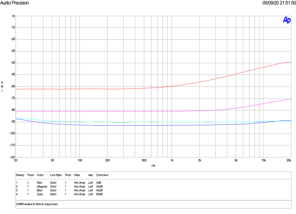
### Common Mode Rejection Ratio
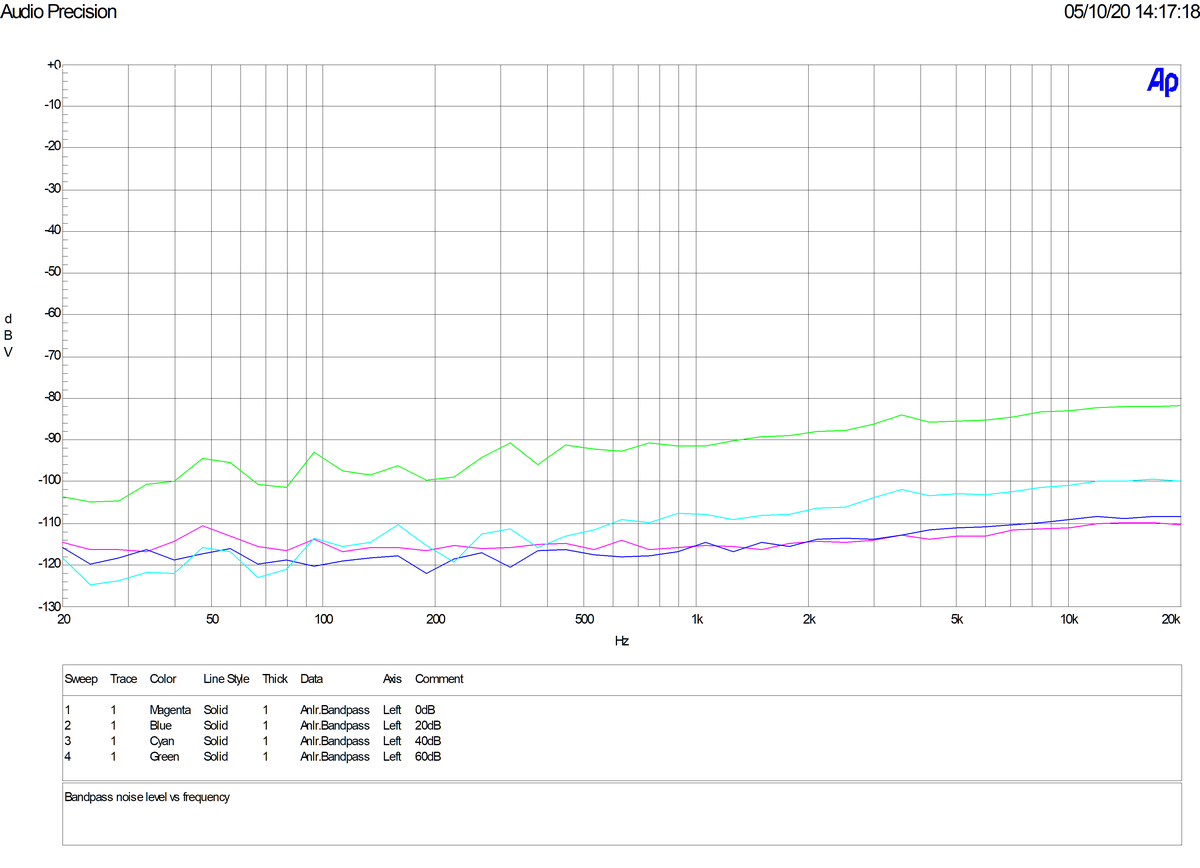
### Bandpass Noise Level
Note no measureable hum.
---
OJG 2020
A simple, high-quality DIY microphone pre-amplifier with switched gain.
The background for this project was that I needed a simple but good microphone preamp for doing acoustic measurements. I needed a switched gain to be able to reproduce the gain setting in a more predictable way than what is possible with a potmeter. I could not find any existing DIY designs, so I decided to make one.
The design is based on the excellent THAT1510 preamp IC. It is also compatible with SSM2019 or INA217. I have followed all THAT's datasheets and app-notes to implement a robust, best-practice design.
A goal was to use simple through-hole parts that I and other DIYers usually have in our parts drawer. So there are no additional IC's or voltage regulators for example, it just uses simple transistors, capacitors and zener diodes for supply filtering and regulation. I selected affordable switches and connectors to keep cost down. Many parts can be substituted without sacrificing performance.
This is an open-source project released under CC-BY-SA-4.0 license. It basically means you can use it as you want as long as you share modifications under the same license, and attribute back to this project. See LICENSE.txt for details.
Specifications
-----
- Microphone preamplifier with switched gain and 48V phantom power.
- XLR input and output connectors.
- Phantom power on/off switch.
- Phase invert switch.
- Gains (dB): 0, 10, 15, 20, 25, 30, 35, 40, 45, 50, 55, 60.
- Gain deviation from nominal: Max +/-0.5dB using E12-series resistors.
- Frequency response: 0/-3dB from 10Hz to 100kHz for all gain settings.
- Impedance balanced output.
- Max output level: 20dBu at 0.1% THD (1kHz).
- THD+N less than 0.005% at 1kHz at 18dBu output level for all gain settings (20-20kHz BW).
- 48V DC power supply required, 30mA max.
* PCB dimensions 75mm x 120mm, fits the Hammond 1455K120x(1455K1201 - Hammond Mfg.) enclosure.
* Gain switch on top of enclosure for easy access.
Schematic
-----
Desktop version:
-----
Rack version:
-----
Measurements
-----
### Output noise vs gain
20-22kHz BW un-wtd, 150ohm source impedance
| Gain(dB) | Output Noise (dBu) | EIN (dBu) |
| --- | --- | --- |
| 0 | -98.5 | -98.5 |
| 10 | -98.2 | -108.2 |
| 15 | -97.8 | -112.8 |
| 20 | -96.8 | -116.8 |
| 25 | -95.6 | -120.6 |
| 30 | -93.2 | -123.2 |
| 35 | -89.8 | -124.8 |
| 40 | -86.8 | -126.8 |
| 45 | -82.6 | -127.6 |
| 50 | -77.8 | -127.8 |
| 55 | -73.1 | -128.1 |
| 60 | -68.3 | -128.3 |
### Frequency Response
### THD+N vs Frequency
### THD+N vs Amplitude
### Common Mode Rejection Ratio
### Bandpass Noise Level
Note no measureable hum.
---
OJG 2020
Last edited:
Hi Jan, and thank you.
Do you mean the THAT517x series gain controller chips?
Because then it wouldn't fulfill the requirement to be simple anymore. They are QFN parts, require a microcontroller, UI design etc.
I'll leave that for another project another time")
Do you mean the THAT517x series gain controller chips?
Because then it wouldn't fulfill the requirement to be simple anymore. They are QFN parts, require a microcontroller, UI design etc.
I'll leave that for another project another time
Really nice project and excellent results. I find using single supply +48V especially interesting.
I'm working on something really similar, but still can't decide how to handle power supply. Usually I would use cheap wall-wart style AC transformer with half wave rectifier and LM7815/LM7915 regulators for +/- 15V rails. In my experience this proven to be simple, cheap and low noise.
However requirement of phantom +48V makes things much more complex.
Boost converter from 15V to 48V? This could introduce some imbalance in rails which isn't best thing with half wave rectifier. Not that cheap.
With external +48V PSU it is straightforward to get phantom. But what about powering op amps? Maybe some kind of virtual earth rail-splitter? +/- 24V would be too high so voltages still need to be regulated. Integrated split-rail switching converters are expensive, rather complex and usually works only with low voltages. Switching noises could be an issue too.
I don't know why I'm not really convinced to single supply op amp operation.
I'm a bit puzzled. Do you have any other ideas or suggestions?
Hi Jan, and thank you.
Do you mean the THAT517x series gain controller chips?
Because then it wouldn't fulfill the requirement to be simple anymore. They are QFN parts, require a microcontroller, UI design etc.
I'll leave that for another project another time
Fair enough!
Jan
Really nice project and excellent results. I find using single supply +48V especially interesting.
I'm working on something really similar, but still can't decide how to handle power supply. Usually I would use cheap wall-wart style AC transformer with half wave rectifier and LM7815/LM7915 regulators for +/- 15V rails. In my experience this proven to be simple, cheap and low noise.
However requirement of phantom +48V makes things much more complex.
Boost converter from 15V to 48V? This could introduce some imbalance in rails which isn't best thing with half wave rectifier. Not that cheap.
With external +48V PSU it is straightforward to get phantom. But what about powering op amps? Maybe some kind of virtual earth rail-splitter? +/- 24V would be too high so voltages still need to be regulated. Integrated split-rail switching converters are expensive, rather complex and usually works only with low voltages. Switching noises could be an issue too.
I don't know why I'm not really convinced to single supply op amp operation.
I'm a bit puzzled. Do you have any other ideas or suggestions?
Would a SilentSwitcher or a SuperRegulator help?
Linear Audio Silent Switcher MkII – diyAudio Store
Super Regulator – diyAudio Store
Jan
I do know both your projects. SilentSwitcher is clever and exceptional piece of circuit. Unfortunately they doesn't really fit my needs. Too big, not ideal voltages and a bit expensive for that use.
I'm designing stage microphone preamp with effect loop for a friend based at THAT 1510 & 1646.
Basically I want to get internal +15V, -15V and +48V from single, standard and simple to use wall wart style supply like 12V DC, 15V AC or 48V DC.
XLR mic in, unbalanced send / return and XLR line out. It needs to be rather compact as I want to fit everything inside Hammond 1590BB.
Probably gonna start my own thread, don't want to hijack this one.
My aha moment came when I realized that since the signals are AC-coupled both on input and output anyway, then 30V and 48V works just as well as +/-15V and 48V.
I pondered using a TLE2426 as rail-splitter, but found it wasn't necessary here. Also another opamp could function both as rail splitter and servo.
The "trick" here is that the "virtual ground" used for reference to THAT1510 is also sent to the cold pin of the XLR output so that any remaining noise on the reference becomes common-mode on the output and is attenuated by the CMRR of the equipment downstream (usually the PC soundcard in my case).
I have started a companion project, using LTSpice to simulate a boost converter from 5V to 48V with the intention of powering it from a standard USB plug.
Thank you!
I pondered using a TLE2426 as rail-splitter, but found it wasn't necessary here. Also another opamp could function both as rail splitter and servo.
The "trick" here is that the "virtual ground" used for reference to THAT1510 is also sent to the cold pin of the XLR output so that any remaining noise on the reference becomes common-mode on the output and is attenuated by the CMRR of the equipment downstream (usually the PC soundcard in my case).
I have started a companion project, using LTSpice to simulate a boost converter from 5V to 48V with the intention of powering it from a standard USB plug.
Probably gonna start my own thread, don't want to hijack this one.
Thank you!
Last edited:
Your schematic shows the XLR connector's pin1 attached to the audio circuit common (aka ground). The XLR pin1 is a shield and should be attached to the metal chassis at the connector. If there is DC phantom power it also should be attached to the chassis connector.
Correct. And since I am using the NC3FBH1, the pin1 and shield is connected together inside the XLR connector.
I'm going to reread Muncy's paper to see if there is anything I've missed. https://www.jhbrandt.net/wp-content/uploads/2018/10/Noise_Susceptibility_in_Analog_and_Digital_Signal_Processing_Systems.pdf
I'm going to reread Muncy's paper to see if there is anything I've missed. https://www.jhbrandt.net/wp-content/uploads/2018/10/Noise_Susceptibility_in_Analog_and_Digital_Signal_Processing_Systems.pdf
Perfectionism can be a curse Sometimes also I catch myself at overthinking circuits that seem to work perfectly already.
I can recommend those three papers:
http://www.ianbell.ukfsn.org/EzTubeMixer/docs/EzTubeMixer/SimpleMixer/grounding101v2.pdf
Grounding and Shielding Audio Devices
Pin 1 Revisited
Phantom power and grounding are really tricky matters.
Still can't decide if its ok to "tie" enclosure and signal grounds with LED and resistor when SW1 turns phantom off.
Sometimes also I catch myself at overthinking circuits that seem to work perfectly already.I can recommend those three papers:
http://www.ianbell.ukfsn.org/EzTubeMixer/docs/EzTubeMixer/SimpleMixer/grounding101v2.pdf
Grounding and Shielding Audio Devices
Pin 1 Revisited
Phantom power and grounding are really tricky matters.
Still can't decide if its ok to "tie" enclosure and signal grounds with LED and resistor when SW1 turns phantom off.
Attachments
According to first paper it's best to reference +48V to enclosure GND.
Latest version of my whole schematics is in attachment. There is a jumper so I have a bit of flexibility. Depending on the results of measurements I can tie grounds or leave them unconnected. Now fun part begins - PCB layout.
I don't have much experience with isolated DC/DC converters but got suggestion that is better to connect them.
By the way - I can't find BOM, what's P/N of lever switches you used?
Attachments
Oh right, my bad. Thank you.
If you want to generate pretty BOMs in KiCad I can recommend you that plugin - KiCad Interactive HTML BOM Plugin Demos | InteractiveHtmlBomDemo
Tips are of course always welcome - Balanced microphone preamplifier with effect loop
If you want to generate pretty BOMs in KiCad I can recommend you that plugin - KiCad Interactive HTML BOM Plugin Demos | InteractiveHtmlBomDemo
Tips are of course always welcome - Balanced microphone preamplifier with effect loop
Hi, I have not set up a Tindie. The gerbers are in the plots folder on the Github page. Upload those to your favorite PCB maker and they will etch it for you. The minimum order is probably a batch of five, maybe you could offer the ones you don't use yourself to other readers of this thread?
Hey,
I just finished my build of this preamp and would like to show and say thank you to OJG for sharing this design.
After using for a few days now, I can say it is working very well.
I did some variations regarding placement of the switches and connectors because I wanted to use a different type of enclosure.
To not change the PCB-layout there was the need to use some cables to extend the distance from PCB-solder pads to the elements.
I was afraid if this would decrease the performance of the preamp, so I decided to solder some pin-headers to the PCB.
This way I was able to use simple PC Jumpers to bridge these connections directly at the headers and do a comparison against offsite and cable extended mounting.
With my (limited) measurement gear I was not able to spot any noticeable weakening; so I went that way.
Here are some pictures of the finished preamp.


The Enclosure is made of two top-covers from old netscreen vpn boxes.
Front- and back plate are cut of some aluminum sheet leftovers I had laying around.
Labelling is drawn in Inkscape, mirrored, printed with a laser printer, ironed to the front plate and finally protected with some clearcoat.
Thanks again,
Nico
I just finished my build of this preamp and would like to show and say thank you to OJG for sharing this design.
After using for a few days now, I can say it is working very well.
I did some variations regarding placement of the switches and connectors because I wanted to use a different type of enclosure.
To not change the PCB-layout there was the need to use some cables to extend the distance from PCB-solder pads to the elements.
I was afraid if this would decrease the performance of the preamp, so I decided to solder some pin-headers to the PCB.
This way I was able to use simple PC Jumpers to bridge these connections directly at the headers and do a comparison against offsite and cable extended mounting.
With my (limited) measurement gear I was not able to spot any noticeable weakening; so I went that way.
Here are some pictures of the finished preamp.
The Enclosure is made of two top-covers from old netscreen vpn boxes.
Front- and back plate are cut of some aluminum sheet leftovers I had laying around.
Labelling is drawn in Inkscape, mirrored, printed with a laser printer, ironed to the front plate and finally protected with some clearcoat.
Thanks again,
Nico
- Home
- Design & Build
- Equipment & Tools
- ThatMicPre - an open-source mic preamp