I am currently trying to convert an old AC clamp meter into an instrument usable for all audio-frequency works.
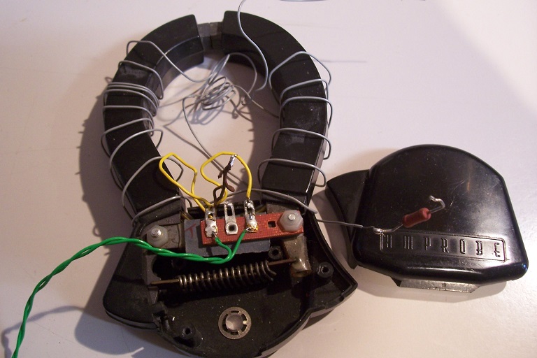
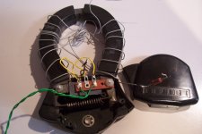
The probe in question was an "Amprobe", probably made end '60s, early '70s and was part of a graphic recorder.
It is of a poor quality standard, and does not work as a real current transformer: its magnetizing inductance acts as a large part of the shunt, and it worked and was calibrated for a single frequency, 60 or 50Hz.
The detector used a selenium rectifier, which even at that time was already antiquated:
By adding a suitable electronic conditioning circuit, I hope to convert this piece of crap into something usable and accurate.
I have measured its characteristics: ~0.5H, DC resistance ~104 ohm.
Even with a perfect transimpedance input, this results in a LF cutoff >33Hz.
As I need 10x better, I have to compensate the winding resistance by a negative resistance.
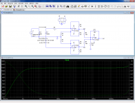
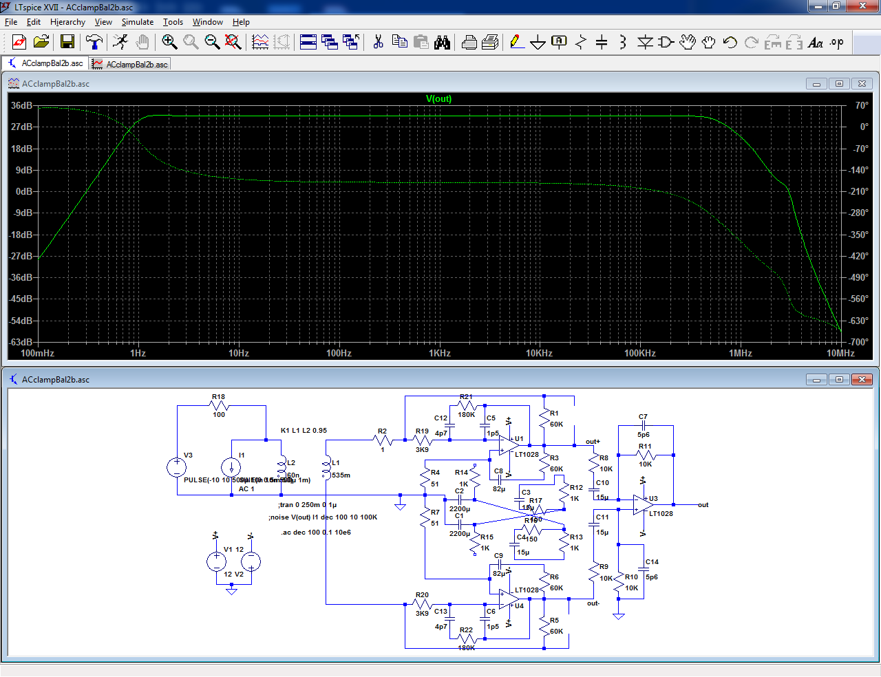
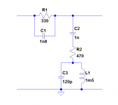
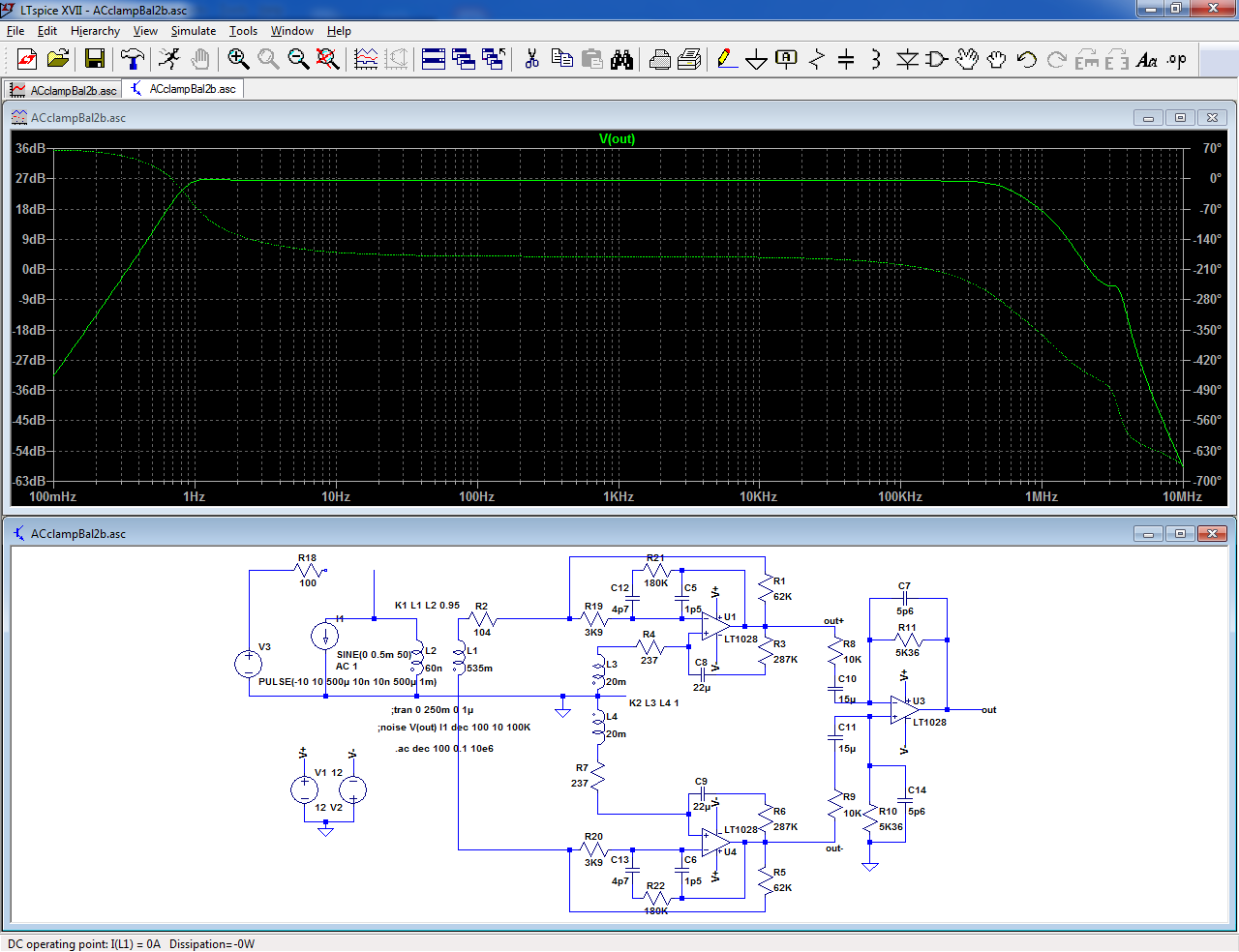
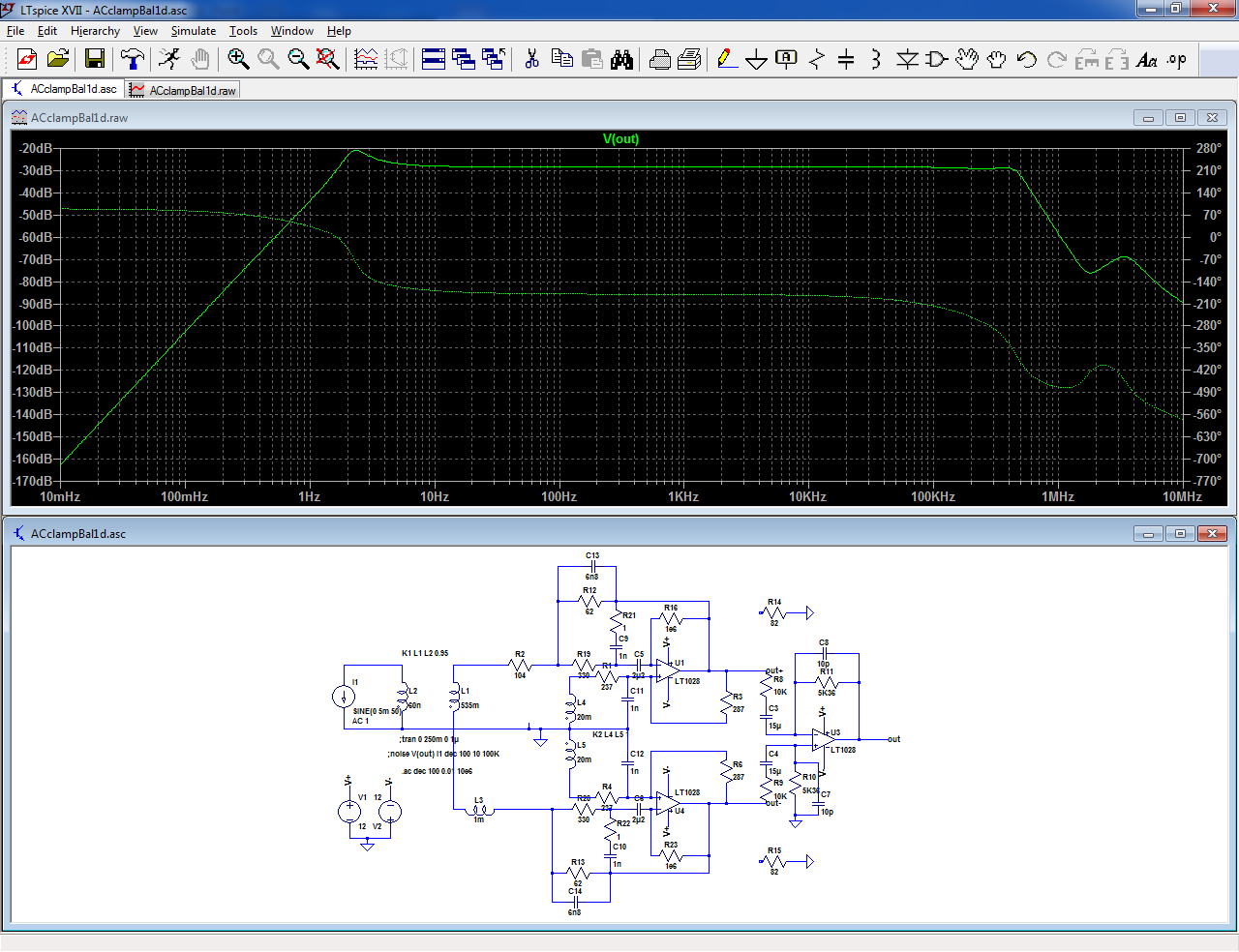
Because of the poor shielding, I have opted for a balanced circuit:
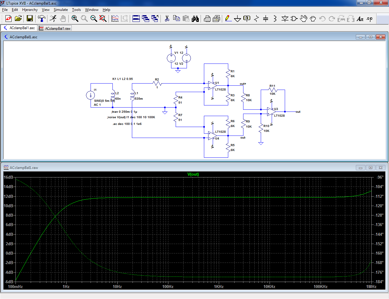
R1, R5 define the gain and R3, 4, 6, 7 provide the negative resistance. R4 and R7 are non-inductive copper windings, to compensate the measurement windings.
The result looks attractive, with a response flat to under 1Hz, but that is in sim only: in reality, the circuit also needs to be DC-stable, which it won't be without additional measures.
The first idea to use a blocking cap in series with the winding is not practicable; the combination of low synthetic resistance with a large inductance and capacitance results in a huge VLF resonance.
An additional pole has to be introduced somewhere, but this is no simple task: if the pole has a frequency comparable to the one already present, it will create a large peak in the response.
The pole can be placed at a much higher frequency, but this will also kill the LF capability, and placing it at a much lower frequency results results in huge time-constants and bulky components.
There is another difficulty: for noise and dynamic range reasons, the range switching should be made directly at the transimpedance stage level.
This means switching the 4 resistors, plus the possible DC-blocking caps for each range, and I intend to implement 5 ranges: from 20mA to 200A.
That is a lot of contacts.
I opted for a tradeoff: the only switching at the TIA would be the unit: mA or A. The resistors would be 60 ohm or 60K.
The 3 subranges would be created downstream, by varying the gain. The 2mA range is probably not going to be usable, but it doesn't matter.
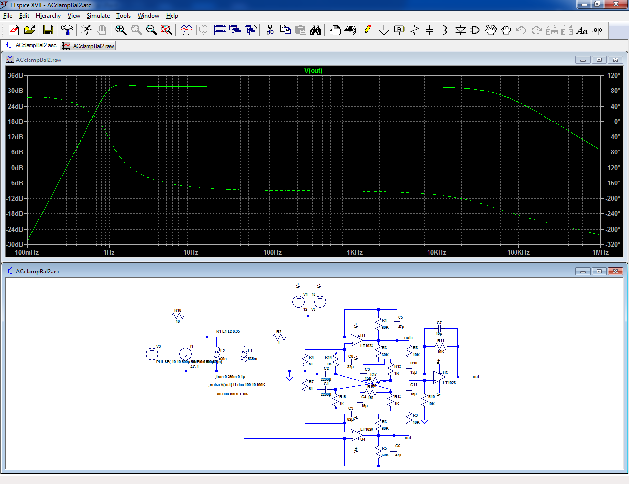
With the 60K, a capacitor would be inserted in series with the positive feedback resistor. This would still result in a DC gain >1000: awkward, but manageable:
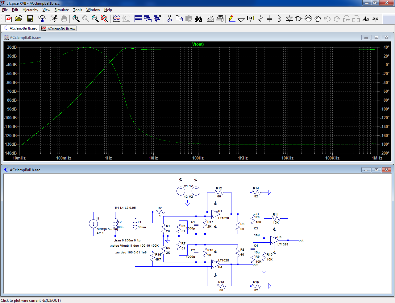
With the 60 ohm, an additional trick is needed to avoid impossibly high capacitor values:
All of this could be made to work, but it is complicated, clumsy and inelegant.
There must be a cleverer way to implement it, but so far I couldn't think of one.
Any creative suggestion is welcome.
The circuit is essentially a zero-field circuit (the clamp is a transformer), but with the complication of multiple ranges
The probe in question was an "Amprobe", probably made end '60s, early '70s and was part of a graphic recorder.
It is of a poor quality standard, and does not work as a real current transformer: its magnetizing inductance acts as a large part of the shunt, and it worked and was calibrated for a single frequency, 60 or 50Hz.
The detector used a selenium rectifier, which even at that time was already antiquated:
By adding a suitable electronic conditioning circuit, I hope to convert this piece of crap into something usable and accurate.
I have measured its characteristics: ~0.5H, DC resistance ~104 ohm.
Even with a perfect transimpedance input, this results in a LF cutoff >33Hz.
As I need 10x better, I have to compensate the winding resistance by a negative resistance.
Because of the poor shielding, I have opted for a balanced circuit:
R1, R5 define the gain and R3, 4, 6, 7 provide the negative resistance. R4 and R7 are non-inductive copper windings, to compensate the measurement windings.
The result looks attractive, with a response flat to under 1Hz, but that is in sim only: in reality, the circuit also needs to be DC-stable, which it won't be without additional measures.
The first idea to use a blocking cap in series with the winding is not practicable; the combination of low synthetic resistance with a large inductance and capacitance results in a huge VLF resonance.
An additional pole has to be introduced somewhere, but this is no simple task: if the pole has a frequency comparable to the one already present, it will create a large peak in the response.
The pole can be placed at a much higher frequency, but this will also kill the LF capability, and placing it at a much lower frequency results results in huge time-constants and bulky components.
There is another difficulty: for noise and dynamic range reasons, the range switching should be made directly at the transimpedance stage level.
This means switching the 4 resistors, plus the possible DC-blocking caps for each range, and I intend to implement 5 ranges: from 20mA to 200A.
That is a lot of contacts.
I opted for a tradeoff: the only switching at the TIA would be the unit: mA or A. The resistors would be 60 ohm or 60K.
The 3 subranges would be created downstream, by varying the gain. The 2mA range is probably not going to be usable, but it doesn't matter.
With the 60K, a capacitor would be inserted in series with the positive feedback resistor. This would still result in a DC gain >1000: awkward, but manageable:
With the 60 ohm, an additional trick is needed to avoid impossibly high capacitor values:
All of this could be made to work, but it is complicated, clumsy and inelegant.
There must be a cleverer way to implement it, but so far I couldn't think of one.
Any creative suggestion is welcome.
The circuit is essentially a zero-field circuit (the clamp is a transformer), but with the complication of multiple ranges
Attachments
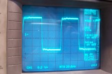
I have continued the real tests, based on the latest simulations, and they seem to fit well with the sim results.
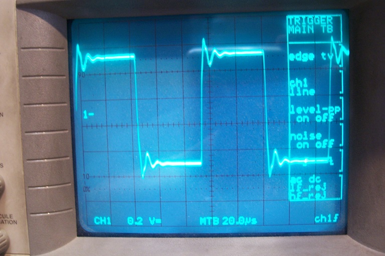
The squarewave response was not to my taste though, and the top of the frequency range will need some attention too.
There are two issues to contend with: the FR itself, which needs some equalization due to the interaction with the parasitic parameters of the transformer, and the isolation from the capacitance of the cable to the clamp.
Some length of cable is inevitable for a convenient use, but its capacitance would connect directly to the inverting inputs of the opamps, which is a recipe for problems.
Here is the fix I found:
It works in sim, and also in reality with somewhat different values, but it adds further complications, and the additional EQ networks need to be switched with the ranges.
Not exactly practical, but it allows a usable BW from ~1.5Hz to 300kHz.
Again, any clever idea leading to simplifications is welcome
Attachments
> idea leading to simplifications is welcome
Considering the size of that clamp, an "obvious simplification" is to put the chip inside the clamp. Now with ultra-short wires it can be single-ended, one opamp. Stray C much less an issue. Since DC response won't happen, it can be single-supply, 3 wires back to a head unit with power.
Considering the size of that clamp, an "obvious simplification" is to put the chip inside the clamp. Now with ultra-short wires it can be single-ended, one opamp. Stray C much less an issue. Since DC response won't happen, it can be single-supply, 3 wires back to a head unit with power.
Thanks, sensible propositions, but I considered them already.
Although the available space looks large, I already have to use it to lodge the ~100 ohm non-inductive compensating copper winding, and it will occupy most of the space.
I could make it smaller, but this would involve winding myself a bifilar coil with 0.03mm wire, certainly doable, but since I have a coil-former garnished with suitable bifilar windings, I would prefer to use it (I hate winding things myself, although I can do it when I have no other option).
Locating the chip inside the probe is an attractive option, but it rules out any range-switching at this level, because of the number of contacts and components involved with the current tradeoff (unless a clever shortcut can be found).
Without switching, the front-end has to be dimensioned for the highest range, 200A, with feedback resistors of 60 ohm and subsequent amplification for lower ranges, which is not ideal for noise performance
I have breadboarded the x1 and x1000 versions of the front-end, and they both worked, with some real-worlds mods compared to the sim, but this is completely normal.
In all cases, I still have a small residual persistent ringing at ~180kHz for the squarewave response, but it is an internal, minor resonance mode of the clamp windings, and I'll have to chisel an EQ network in the post-amplifier to have a perfectly clean response.
Since no magical solution emerged, I think I am going to use two complete, switchable frontends for the two super-ranges: it will be simpler and cleaner than switching all the passives with a single pair of opamps.
Opamps aren't expensive, and I will use a 5532 with a discrete buffer for the 200A, and a good FET one for 200mA (still to be decided, TLO72 and the like are definitely too weak).
The 2mA range might be usable in the end.
BTW, I used a balanced configuration to cancel direct electrostatic influences on the windings, not for improving the cable connection between the clamp and the conditioner.
The windings were made for mains operation, with little regard for parasitic capacitances, direction of the winding, etc.
You could use a chopper stabilized amp to deal with DC offset and drift. Some of the latest are hybrid designs with extended bandwidth and only a small leakage of the chopper in the output.
You may already have looked at Tek's current probe amp http://w140.com/mmm/tek-134.pdf It does get 17Hz out of a probe with a native response of 120 Hz.
You may already have looked at Tek's current probe amp http://w140.com/mmm/tek-134.pdf It does get 17Hz out of a probe with a native response of 120 Hz.
Having a DC-coupled conditioning would be ideal: no coupling caps, no tradeoffs about VLF peaking, etc.
I didn't consider it, because even a good conventional opamp like the OP77 isn't up to the task, and in my mind, chopper stabilized opamps always leak some nasties, but if the technology has improved, it is certainly worth examining it.
Thanks for drawing my attention to that option.
If I interpreted the schematic correctly, the probe is used as a conventional current transformer, with a post-equalization to achieve the LF extension.
Probably the simplest solution available at the time, with a custom-designed probe.
The negative-resistance method I use is more complex, but it pushes the correction capabilities further.
Hi Elvee,
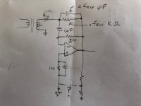
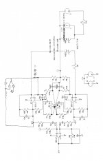
I did something similar sometime in the ’74-’80 era. Customer specs required 1Hz to 70kHz bandwidth. I used a high u toroid core, so the L and series R “native” corner frequency was already below 1Hz and so I didn’t need to incorporate any negative resistance. My inspiration was a “design idea” in one of the trade magazines about low-frequency current transformers by Tom Gross.
The attached pic shows my solution to the dilemma of gain x offset as best I recall: unity gain DC bias. The corner frequency of the bias path needs to be below the L/series R corner for acceptable low-frequency damping. My intuition is that the circuit might also be stable with some synthesized negative resistance (shown as an optional connection), but this needs confirmation as my intuition fails me frequently.
Steve
Attachments
I have simulated the configuration: with the high-current superrange (60 ohm feedback), it works like a charm. I had to use a 2.2µF cap to arrive at the same LF performance as the initial circuit, but it is perfectly tolerable.
With the 60K feedback, things turn sour, and even with insane values (10M, 4.7µF), the rolloff start at around 10Hz.
Something wrong with the interactions of impedances, I do not know exactly what
With the 60K feedback, things turn sour, and even with insane values (10M, 4.7µF), the rolloff start at around 10Hz.
Something wrong with the interactions of impedances, I do not know exactly what
I remade the noise sims to leave no stone unturned, but the result is punishing even with a LT1028: depending on the frequency, the penalty is comprised between 5 and 20.
I have made an attempt at 2mA FS (with the 60K, of course), and it looks practicable, at least from a noise POV.
The hum is atrocious, because the magnetic circuit is long and flimsy and catches every bit of field leaked in the vicinity, but it could be usable in the right environment (my lab as it is does not qualify).
I have made my choice: I will use two frontends with the 60 ohm one using Steve's proposition, and the 60K one my initial circuit with the caps in the positive feedback path. They are sufficient to make the amplifiers DC-stable.
The DC point is not very well defined, but since the rest is AC-coupled, it does not really matter.
Of course, using a single, DC-coupled frontend would be better if possible, but although the equalizations for the two situations are similar, they cannot be fused in a single network and would need to be switched anyway.
The secondary winding has a relatively nasty behavior, which is not easily modeled with lumped parasitics, and the length of the winding causes transmission line effects which are not simple to compensate with lumped components, but it is possible to arrive at an acceptable result using simple means, if some ripples are tolerated.
This is the uncorrected 10kHz squarewave response:
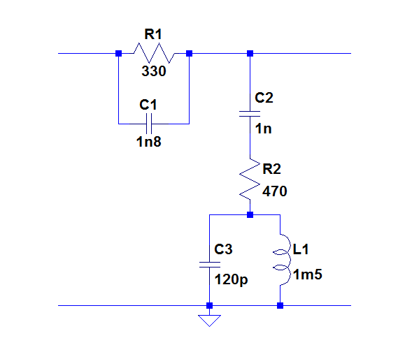
It is corrected with this network:
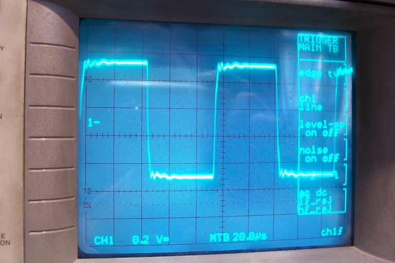
And the (provisional) result is this:
At this stage, I am not going to refine the circuit too much, as the final implemention will have some effect
The DC point is not very well defined, but since the rest is AC-coupled, it does not really matter.
Of course, using a single, DC-coupled frontend would be better if possible, but although the equalizations for the two situations are similar, they cannot be fused in a single network and would need to be switched anyway.
The secondary winding has a relatively nasty behavior, which is not easily modeled with lumped parasitics, and the length of the winding causes transmission line effects which are not simple to compensate with lumped components, but it is possible to arrive at an acceptable result using simple means, if some ripples are tolerated.
This is the uncorrected 10kHz squarewave response:
It is corrected with this network:
And the (provisional) result is this:
At this stage, I am not going to refine the circuit too much, as the final implemention will have some effect
Attachments
Hi Elvee,
Very nice work!
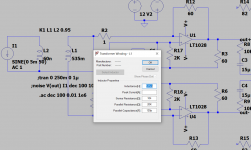
At this inconveniently late date, I have another thought--- a so-called “DC servo” sometimes wrapped around audio power amps.
On the notion that a sketch is worth a thousand words, I’ve pasted one possibility into your schematic. There would be an identical network around U1 but I didn’t bother to sketch it. Since it forces 0 gain at DC (sub-Hz bandwidth), the servo would probably behave similarly to the circuit in my first picture and may not offer any advantage. But with the servo scheme, I thought you might devise the unified, gain-switched design you prefer.
BTW, I have a couple Amprobes inherited from my dad, one with a stuck meter movement. Maybe it will become another project.")
Best,
Steve
Very nice work!
At this inconveniently late date, I have another thought--- a so-called “DC servo” sometimes wrapped around audio power amps.
On the notion that a sketch is worth a thousand words, I’ve pasted one possibility into your schematic. There would be an identical network around U1 but I didn’t bother to sketch it. Since it forces 0 gain at DC (sub-Hz bandwidth), the servo would probably behave similarly to the circuit in my first picture and may not offer any advantage. But with the servo scheme, I thought you might devise the unified, gain-switched design you prefer.
BTW, I have a couple Amprobes inherited from my dad, one with a stuck meter movement. Maybe it will become another project.
Best,
Steve
Attachments
What I have in mind is a general-purpose, bench instrument mainly aimed at audio, PSU and similar applications: visualizing the waveforms of the collectors current in an OP stage, the charging pulses in the smoothing capacitor of a conventional DC supply, the inrush current of a transformer, etc.Elvee, just taking a step back to the range of applications you may have had in mind, was this aimed at non-contact audio current measurement, as per some of the cheap LEM current sense modules that are nowadays in common use in switchmode power supply pcbs?
I have had this thing lying around for many years, and I thought that the wide jaw opening combined with the relatively slim core would make it handy for practical use.
The fact that its parameters allow for a relatively large max current (200A rms) together with a good sensitivity and dynamic range (minimum FS range 20mA or even 2mA) was also a factor that decided me.
I already have a number of other probes, but I thought this one would add something else.
I have already considered and tested this option in sim, but with a plain-vanilla scheme, it requires to push the pole of the servo at impossibly low-frequencies, resulting in time-constants in the tens of seconds.At this inconveniently late date, I have another thought--- a so-called “DC servo” sometimes wrapped around audio power amps.
On the notion that a sketch is worth a thousand words, I’ve pasted one possibility into your schematic. There would be an identical network around U1 but I didn’t bother to sketch it. Since it forces 0 gain at DC (sub-Hz bandwidth), the servo would probably behave similarly to the circuit in my first picture and may not offer any advantage. But with the servo scheme, I thought you might devise the unified, gain-switched design you prefer.
There could be way to avoid that, like a higher order filter, but I don't feel I am competent enough to tackle the resulting stability issues.
The unused components on the schematic are the remains of another, local DC servo scheme I also tested -but abandoned in the end-
If they belong to an instrument similar to the one I pulled mine off, the stuck meter is the normal condition: it is part of the printing process.BTW, I have a couple Amprobes inherited from my dad, one with a stuck meter movement. Maybe it will become another project.
Most of the time, the writing needle is pushed against the paper, and as a result the galvanometer is stuck.
Regularly, the pen is lifted, and the movement is allowed to move to another position.
Last edited:
An unexpected enigma
I am in the process of quietly finalizing the instrument, and as I tackled the equalizations and calibrations, I noticed something strange: the gain (transimpedance) was higher than initially calculated.
For the low-current section (mA), the discrepancy was moderate, a bit over 10%, which is not particularly shocking, since I crudely estimated the transformation ratio, knowing that this would be refined and calibrated later.
For the high-current path (A), the discrepancy was in a 1 : 2 ratio, completely inexplicable.
I first looked for material errors: wrong component value, wrong connections, etc, but everything looked perfectly legit.
I then made simulations, and the problem was also present.
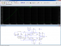
This is the low-current section:
The behavior is normal.
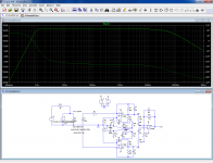
This is the high-current section:
The level should be 60dB lower than in the previous case, but it is -28dB instead of -33dB.
In fact the negative resistance, even accurately compensated seems to boost the gain of the transimpedance amplifier, and the 62 ohm resistors become in fact ~100 ohm.
The effect is really not obvious at all, and it took me some time to realize what was happening.
At first I had thought that the anti-series compensation winding created the effect, but it is just the combination of the various resistances in the circuit
I am in the process of quietly finalizing the instrument, and as I tackled the equalizations and calibrations, I noticed something strange: the gain (transimpedance) was higher than initially calculated.
For the low-current section (mA), the discrepancy was moderate, a bit over 10%, which is not particularly shocking, since I crudely estimated the transformation ratio, knowing that this would be refined and calibrated later.
For the high-current path (A), the discrepancy was in a 1 : 2 ratio, completely inexplicable.
I first looked for material errors: wrong component value, wrong connections, etc, but everything looked perfectly legit.
I then made simulations, and the problem was also present.
This is the low-current section:
The behavior is normal.
This is the high-current section:
The level should be 60dB lower than in the previous case, but it is -28dB instead of -33dB.
In fact the negative resistance, even accurately compensated seems to boost the gain of the transimpedance amplifier, and the 62 ohm resistors become in fact ~100 ohm.
The effect is really not obvious at all, and it took me some time to realize what was happening.
At first I had thought that the anti-series compensation winding created the effect, but it is just the combination of the various resistances in the circuit
Attachments
- Status
- This old topic is closed. If you want to reopen this topic, contact a moderator using the "Report Post" button.
- Home
- Design & Build
- Equipment & Tools
- Ideas to improve a zero-field transformer based circuit