I'm not sure there is a reason to try to speed up the spark if the step up trafo has >250KHz Fs.
My taser output resistance is 76 ohms. Factoring in the potted trafo leakage inductance, I would think that the increased capacitance of coax would actually slow down the spark. This was much more evident with the coilpack which has a 10kohm output resistance.
A shield does make sense for the 20KHz flyback noise. For the common mode noise, maybe a small capacitor after the internal spark gap would help, if it didn't rip itself apart from the stresses.
The ground plane method does look better and better. It eliminates microphone booms and structures around the spark gap and I think this is why the ground plane measurements were much better looking. But I suppose you could calibrate the microphone and boom together if they were never going anywhere, and glue all the joints...
I just found this discussion on spark gaps and low jitter HV pulses. http://citeseerx.ist.psu.edu/viewdoc/download?doi=10.1.1.829.9852&rep=rep1&type=pdf
Its way beyond anything I want to explore but the notes on the spark gap are very interesting, especially on the distorted field version.
My spark generator is due tomorrow. Should be interesting, I hope.
Its way beyond anything I want to explore but the notes on the spark gap are very interesting, especially on the distorted field version.
My spark generator is due tomorrow. Should be interesting, I hope.
In the same vein, this NASA paper describes the process of spark breakdown and various ways of improving the delay time of GDTs:
DTIC ADA214199: Technology of Fast Spark Gaps : Defense Technical Information Center : Free Download, Borrow, and Streaming : Internet Archive
DTIC ADA214199: Technology of Fast Spark Gaps : Defense Technical Information Center : Free Download, Borrow, and Streaming : Internet Archive
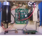
I got the spark generator in today and managed to figure out how to cheat it into generating a spark on trigger. Inside its a traditional ignition coil with a solid state drive. The spark is pretty substantial.
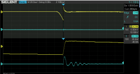
The lower trace is the spark current resonating in the ign. coil inductance. The peak current is around 1A. The duration is longer than a microsecond it seems but I still have more to research on this guy, now that I know how to get a spark on command.
The lower trace is the spark current resonating in the ign. coil inductance. The peak current is around 1A. The duration is longer than a microsecond it seems but I still have more to research on this guy, now that I know how to get a spark on command.
Attachments
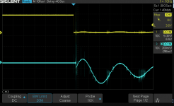
The ticks after the discharge resemble aftersparks on a spark plug waveform. They follow the polarity of the rate of change of current which would seem to suggest the output voltage is 90 degrees off the input current.
I found for my ignition coil the input had a resonance around the treble region but the input impedance had a notch at 250KHz which was the output voltage peak. Maybe there is a snubber at work causing the LF resonance but allowing a HF peak?
I found for my ignition coil the input had a resonance around the treble region but the input impedance had a notch at 250KHz which was the output voltage peak. Maybe there is a snubber at work causing the LF resonance but allowing a HF peak?
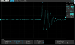
I went back and cleaned some things up. First was to improve the trigger connection but still work to do there. Second was to twist the spark output cables. big improvement and a lot of the ring went away. This is across a 1/4" gap. I also calibrated the current probe and figured out how to scale it properly. The peak current is pretty reliably 50 A. The spark duration seems to be around 50 nS for the first peak and less than a microsecond overall duration.
More tomorrow after chores. . .
More tomorrow after chores. . .
Attachments
I see twisting the cables reduced the ringing but did not change it's frequency much. Can you see if a cable clamp ferrite on the spark leads or power cable has an effect?
15MHz is about the frequency I tend to get for common mode resonances in my lab. That corresponds to a 20 meter wavelength. The 1/4th wavelength antenna mode would be 5 meters.
15MHz is about the frequency I tend to get for common mode resonances in my lab. That corresponds to a 20 meter wavelength. The 1/4th wavelength antenna mode would be 5 meters.
Last edited:
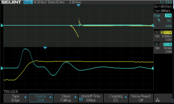
I setup the HV probe to get a better idea of what is happening. The gap was reduced to 3 mm?and here is what I got- upper trace 20 uS/div and lower magnified trace 100 nS/div. You can see the voltage build up and then arc pretty consistently. The current coincides with the voltage dropping. And then junk rattling at a low level for some time afterward. However no spark no current.
There are variations but probably due to wind currents etc.
Now I need to know which software and how to set it up for the acoustic measurements. What I was planning may not work. This was quite a project already.
There are variations but probably due to wind currents etc.
Now I need to know which software and how to set it up for the acoustic measurements. What I was planning may not work. This was quite a project already.
Attachments
I have been recording with audacity. I set the sparker going, and glance at the screen to see if I am in the goldilocks zone in case I need to change the distance. So I get a recording with many sparks.
I also have the RTA going in REW as that allows me to see if I am getting overload or interference, so I can immediately find the best spark distance.
That gives me two channels (from the same mic) in Audacity which I mix together, then duplicate. The second channel I apply a 200Hz lowpass filter, then normalize (all in 32 bit float). The first channel I leave raw as an SPL reference. The lowpass filter works better with the entire recording than with individual doublets. The same is true if you want to add a rumble filter, but this filter should have a Fc lower than the lowpass filter otherwise you create a bandpass filter where the filters intercept.
Then I export both channels to a 24 bit WAV and open in REW beta (which opens the channels are separate measurements). Instead of selecting sparks individually in audacity, I just export the raw doublet and lowpassed doublet recordings with all the sparks into a 2 channel file. Then I simply slide the FFT window around in REW to choose a good spark. This is in the beta version, I don't think the stable version has this feature.
To scout out sparks in REW you click the IR windows button at the top and apply some windowing. The frequency-dependent window is convenient for scouting doublets. Then you go to the impulse response pane and slide the blue arrow at the top of the chart. One good way to do this is to find a spark that looks good, note it's time from the X axis and enter that time into the window center field in the IR windows box. That will move the window to the spark you selected. I like to slide the window around to see the reponse before and after to gauge the background noise influence on a particular spark.
After you found a good spark, you will want to click the "set T=0 at cursor" button with the cursor at the window center, and then set the window center to zero to put the window back in the right place. This will give you correct absolute phase information in the SPL chart. However REW doesn't process unexpected files like this well, so there will be some phase glitches. I fix this by exporting the impulse response with rectangular windowing, which gives me a .wav file with just the spark I selected. I then import that as an impulse response and REW treats it normally.
Here is an example REW file. First measurement is the raw doublet recording, second is the lowpassed recording. The Impulse pane allows you to zoom in on individual sparks and slide around the left and right windows and window center.
Spark Calibration in REW Beta - Google Drive
REW beta download:
Downloads | AV NIRVANA
Spark Calibration in REW Beta - Google Drive
REW beta download:
Downloads | AV NIRVANA
Last edited:
I have invested what little free time I could in adapting a real trigger circuit to the box. The included "trigger" is an enable for the line sync sparks. Nice but not usable for me really. So after some fiddling I grafted a comparitor into it connected such that a pulse in will generate a spark out. it works pretty well.
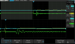
The waveforms below confirm the spark-
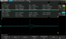
15KV discharge over 35 nS and a current of 35 A (actually more than the probe P6021 is rated for). So a pretty energetic and short discharge. Cleaning up the wiring and putting the steel cover back on cleaned up the ringing a lot.
And here is the spark acoustic output from a B&K 4136 microphone. now for the acoustic pressure calculation- the capsule is 1.27 mV/PA. The peal to peak is about 2V or 60 dB over 94 dB-1PA. or a peak of 150 dB spl?
I need to confirm the accuracy of all of this another tedious effort coming up. Still it seems the acoustic event is 40 uS long, so 50 KHz is certainly possible. The microphone is tuned flat pressure to 80 KHz and then drops quickly. I'll swap to the free field 4135 tomorrow and see what I see. To really check the HF I'll need to remove the grid, but that won't happen until I have everything else at a good state. These capsules are way too fragile with the grid off to be casual.
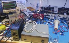
Final pic is the test setup, which is far from ideal. The QA401 generates the trigger pulse and the scope triggers on the spark voltage. The mike output is about 200 uS later.
Next steps are to make a real spark discharge fixture and then integrate it all into an acoustic measurement setup.
The waveforms below confirm the spark-
15KV discharge over 35 nS and a current of 35 A (actually more than the probe P6021 is rated for). So a pretty energetic and short discharge. Cleaning up the wiring and putting the steel cover back on cleaned up the ringing a lot.
And here is the spark acoustic output from a B&K 4136 microphone. now for the acoustic pressure calculation- the capsule is 1.27 mV/PA. The peal to peak is about 2V or 60 dB over 94 dB-1PA. or a peak of 150 dB spl?
I need to confirm the accuracy of all of this another tedious effort coming up. Still it seems the acoustic event is 40 uS long, so 50 KHz is certainly possible. The microphone is tuned flat pressure to 80 KHz and then drops quickly. I'll swap to the free field 4135 tomorrow and see what I see. To really check the HF I'll need to remove the grid, but that won't happen until I have everything else at a good state. These capsules are way too fragile with the grid off to be casual.
Final pic is the test setup, which is far from ideal. The QA401 generates the trigger pulse and the scope triggers on the spark voltage. The mike output is about 200 uS later.
Next steps are to make a real spark discharge fixture and then integrate it all into an acoustic measurement setup.
Attachments
Today I experimented with trying to get sox (on linux) to automatically record sparks into numbered files by triggering on the audio. The output files are therefore time aligned within one sample so I can record hundreds of them in one go and mix them together in Audacity. At 192k the error of one sample is unlikely to affect the audio band. But perhaps with DSP they could be aligned more accurately. I suppose it may be possible to do this in REW if all files are opened, T=0 automatically set and then merged.
In audacity I can quickly scan for outliers and delete them before mixing all recording down into a single spark.
The result is attached. Unlike the results with a single spark, less aggressive windowing is needed and so the frequency resolution is better.
Oddly, in order to get rid of what seemed like acoustic overload, I had to actually get closer to the mic. Maybe getting closer makes the overload more symmetrical therefore canceling the DC component? And I really need to be much father away? This thing keeps me guessing.
Attachments
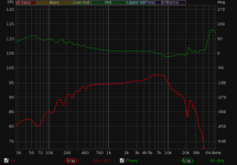
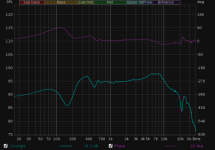
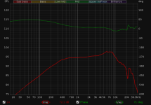
Here is an averaged spark compared to a single spark with the same windowing.
The 500Hz drop off is caused by a 500Hz filter. It may appear that I could get response to 20Hz by removing the filter, but actually the response below 500Hz is dominated by interference from the spark generator which mimics a flat response. However it does look like the response could be extended much lower with averaging if the interference problem is taken care of.
The 500Hz drop off is caused by a 500Hz filter. It may appear that I could get response to 20Hz by removing the filter, but actually the response below 500Hz is dominated by interference from the spark generator which mimics a flat response. However it does look like the response could be extended much lower with averaging if the interference problem is taken care of.
Attachments
Oddly, in order to get rid of what seemed like acoustic overload, I had to actually get closer to the mic. Maybe getting closer makes the overload more symmetrical therefore canceling the DC component? And I really need to be much father away? This thing keeps me guessing.
If the energy I measured is correct you could well be overloading the microphone. the overload point on the 4136 is listed as 165 dB @ 3% distortion. That is close to what i measured. I'll do a cal to make sure there is no cal errors. if correct you could be way past the max limit on the Primo microphone.
My computer mic input seems to be 0.775Vrms or 1.096Vp at 0dbFS. For a spark recorded at 26db gain, the peak value was 63% of max. So
1.096V * -26db * 0.63 = 34.62mVp
The EM172 sensitivity is -28db at 1PA which is 94db SPL, so
34.62mVrms / -28db * 94db = 92.77dbSPL peak
Or 92dbSPL peak for the recorded spark. So if my math is right the microphone may be starting to show nonlinearity but I don't think it is clipping. Abrupt clipping is obvious as it causes a massive DC component in the impulse response. Usually electrical interference dominates before that point.
My spark lengths are usually below 2mm.
I'm going to switch current transformers since I'm probably saturating the P6021. Then I can get a peak power. The sparks from this setup are pretty loud. They get louder with a bigger gap. When I run the system on its internal clock with the voltage probe attached the scope crashes and reboots. Too much EMI.
My measurements were quite close in (2") so they would be loud. Opening the gap makes them louder. more measurements coming.
My measurements were quite close in (2") so they would be loud. Opening the gap makes them louder. more measurements coming.
- Home
- Design & Build
- Equipment & Tools
- Spark calibration of microphones