Here is an interesting article on ultrasonic condenser microphones:
Microphones
Interesting idea to use a watch spring and/or balance wheel for the backplate. Also, CRT shadow mask material.
Microphones
Interesting idea to use a watch spring and/or balance wheel for the backplate. Also, CRT shadow mask material.
Last edited:
Interesting work. Keep in mind that most of the work is almost 50 years old. Still not much has changed. I could not figure out where the commercial microphones he described were sold.
In doing a little research a found this https://www.knowles.com/docs/default-source/model-downloads/spu0410lr5h-qb-revh.pdf Here Heterodyne Ultrasonic Bat Detector – MarcelMG Blog – electronics, engineering and more available here Digikey for $0.76. Things have moved a lot in 50 years. One huge virtue of Mems transducers is very high reproducibility. The variations in sensitivity and response are quite small.
In doing a little research a found this https://www.knowles.com/docs/default-source/model-downloads/spu0410lr5h-qb-revh.pdf Here Heterodyne Ultrasonic Bat Detector – MarcelMG Blog – electronics, engineering and more available here Digikey for $0.76. Things have moved a lot in 50 years. One huge virtue of Mems transducers is very high reproducibility. The variations in sensitivity and response are quite small.
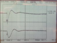
I have the coil drive pretty well optimized now. This is with 50 Ohms between the coil and the cap. The 87 Ohms might be better but this is close enough I think. I'm getting very clean sparks it seems. The current duration is about 50 uS. Does that mean the period between the pulses of the doublet is around 50 uS? That would translate to around 20 KHz? maybe including the finite nature of air etc. could explain the 30 KHz limit?
I could build a different sparker using a resistor, caps and a high voltage supply but I'm not sure it would be better. Here is a youtube on such an effort How to model a spark gap in LTSpice - YouTube The challenge is staying awake. Still its pretty good.
I could build a different sparker using a resistor, caps and a high voltage supply but I'm not sure it would be better. Here is a youtube on such an effort How to model a spark gap in LTSpice - YouTube The challenge is staying awake. Still its pretty good.
Attachments
Well going on the theory, the more energy in the discharge the longer the period of the N-wave, meaning a lower HF limit. This is because when the maximum compression of air is reached, the only other way to expand is in wavelength.
The fact that the coil continues to ring after the spark suggests that it is no longer shorted by the spark. There may be some glow discharge extending the doublet period, perhaps smoothing the negative tooth of the doublet and therefore filling in the nulls (but maybe N-waves don't work that way). If it works this way then this may be why a coil seems to give different results than a direct discharge from a capacitor.
If the ringing is fast enough without decay then the next peak may keep the spark alive.
It is the bright plasma which creates the gaseous cavity in which the doublet expands and implodes (if I interpret the literature correctly), so it is the current spike and not the trailing voltage decay which produces the main peak of the doublet.
I had a similar thought that since the discharge event had a 2-3 sample width in the recording, maybe that could be extrapolated to the HF limit of the doublet.
Last edited:
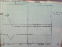
At the spark gap. The upper tace is a Hantex ignition probe and the lower trace is the current from a current transformer. I am not sure what to make of the upper trace. I guess I'll set up the p6015 to compare. The lower trace is around 50 mA/div. Not a scaling this scope supports. In any case the current is gone in less that 200 nS. No second arc (I checked).
Attachments
Hanteck probe going back not suitable for this. may work for older car ignition.
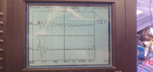
Upper trace is current not sure on the calibration. Lower trace is the voltage at the arc from P6015.
Now that its all working time to rework the spark gap and remove all the stuff that will degrade the quality of the shockwave with near field reflections.
Upper trace is current not sure on the calibration. Lower trace is the voltage at the arc from P6015.
Now that its all working time to rework the spark gap and remove all the stuff that will degrade the quality of the shockwave with near field reflections.
Attachments
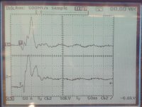
So the discharge is over much faster than the blip I see on the recordings. I figured this might be the case but it is obvious now.
It looks like there is some 60MHz oscillation at the beginning of the discharge. That is a quarter wavelength of 1.25 meters, maybe related to the coax.
It looks like there is some 60MHz oscillation at the beginning of the discharge. That is a quarter wavelength of 1.25 meters, maybe related to the coax.

1.25 meter seems about right for the COAX. Its 75 Ohm coax and i have a 50 Ohm series resistor at the spark end. I need to get some 1/2W CC 75 Ohm resistors.
I don't think that time has much relationship to the acoustic shock wave duration.
I will be replacing the cable with a connectorized version to make this more manageable soon. In the meantime I'm dealing with scope upgrades etc.
I don't think that time has much relationship to the acoustic shock wave duration.
I will be replacing the cable with a connectorized version to make this more manageable soon. In the meantime I'm dealing with scope upgrades etc.
I tried this again on a new microphone. The Takstar CM-63. This microphone seems fairly forgiving of the spark interference in this process.
https://www.amazon.com/TAKSTAR-Instrument-Microphone-Professional-Gold-Plated/dp/B0C58XZ9RS?th=1


This was with the window AC running, since Texas is in deep fry mode. It wasn't at full blast since it was night and it's an inverter AC. This was the result of 100 sparks averaged together.

Controlling the interference is a huge issue, at least with my consumer grade equipment grafted together. The EMP causes an electrical impulse before the acoustic doublet wave hits, so the EMP becomes a step in the final impulse when the lowpass filter is applied. If the EMP is strong enough to cause demodulation then the step will become a sawtooth. This affects the midrange accuracy of the results.
My results are consistently droopy at 10k and above, compared to what the datasheets usually say. One reason for this could be electronic overload, compressing and widening the impulse, but moving the spark away does not always help. Assuming that some null in the output corresponds to a bessel function null does not seem to produce results that are any better. low-energy igniter type sparks seem to be a different beast with a different set of rules. But I don't have a Gefell mic to know for sure.
Averaging improvement of lower BW follows square root addition of noise, so if I get the lower frequency limit down to 1KHz with 100 sparks, to get to 500Hz I need 400 sparks. 250Hz, 1600 sparks. If the rig holds up for that long, it's doable. However room reflections become the limiting factor.
Here are various trial runs.

https://www.amazon.com/TAKSTAR-Instrument-Microphone-Professional-Gold-Plated/dp/B0C58XZ9RS?th=1
This was with the window AC running, since Texas is in deep fry mode. It wasn't at full blast since it was night and it's an inverter AC. This was the result of 100 sparks averaged together.
Controlling the interference is a huge issue, at least with my consumer grade equipment grafted together. The EMP causes an electrical impulse before the acoustic doublet wave hits, so the EMP becomes a step in the final impulse when the lowpass filter is applied. If the EMP is strong enough to cause demodulation then the step will become a sawtooth. This affects the midrange accuracy of the results.
My results are consistently droopy at 10k and above, compared to what the datasheets usually say. One reason for this could be electronic overload, compressing and widening the impulse, but moving the spark away does not always help. Assuming that some null in the output corresponds to a bessel function null does not seem to produce results that are any better. low-energy igniter type sparks seem to be a different beast with a different set of rules. But I don't have a Gefell mic to know for sure.
Averaging improvement of lower BW follows square root addition of noise, so if I get the lower frequency limit down to 1KHz with 100 sparks, to get to 500Hz I need 400 sparks. 250Hz, 1600 sparks. If the rig holds up for that long, it's doable. However room reflections become the limiting factor.
Here are various trial runs.
I still try this every now and then. Here is the evolution of today's experiments:

The long orange line is the manufacturer's calibration file. It's very different from what I measure. I've seen something like this a lot when doing this and it's hard to find a satisfying explanation.
The long orange line is the manufacturer's calibration file. It's very different from what I measure. I've seen something like this a lot when doing this and it's hard to find a satisfying explanation.
I was able to do a sanity check with a friend's Umik-1. The yellow line is the mic's provided calibration, the orange line is from sparks (not much low end because there was a lot of unavoidable LF noise). They're quite close, so now I have more reason to question the manufacturer calibration of the last mic.

- Home
- Design & Build
- Equipment & Tools
- Spark calibration of microphones