Is the gist of it that compressed air gets hotter which increases the pressure, so the compliance in the positive direction is more than you would predict if you just assumed compliance is proportional to absolute pressure?
I remember this came up in speaker stuffing discussions. Do you have a relevant reference?
I remember this came up in speaker stuffing discussions. Do you have a relevant reference?
A Study of acoustic radiation from an electrical spark discharge in air (1974)
By Robert Edward Klinkowstein (Equation 33 appears to be wrong, the cosine term does not have the same roots as the bessel function it replaces)
http://dspace.mit.edu/bitstream/handle/1721.1/13778/24459264-MIT.pdf?sequence=2
There's more than that wrong, I think he was doing some simplifying to show the general shape. Remember back then you still had to use the CRC tables of integrals to look up the values of J1(). Any of the free signal processing programs has it built in.
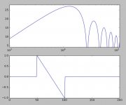
The broken equation put the frequency nulls in the wrong places, but the bessel function min and max given in the paper matched what I got from Wolfram Alpha. Once that is corrected, I can conceive that there could be errors in the matching of the <BW and >BW sections of the spectrum which are computed separately. But I am out of my depth in trying to spot any more errors.
Today I found a salvaged MJW16206 and used it to trigger the coilpack. Spark trains are much less frequent.
I used some vintage 3/8" thumbtacks to make electrodes with the curved surfaces. I guessed that this would have an axial horn like effect and it did boost the ultrasonic frequencies (and the thumbtacks rung like bells). It seems to me this would be a useful method for improving the response just before the first peak, if you could take calibrated measurements and design the electrode shapes.
I can only assume this effect would also be present if using balls as electrodes. The circumferential resonance mode is 20KHz for a 5.5mm ball, so you would want to use quite small ball electrodes.
In my measurements I don't see obvious nulls from a bessel function. If they are there they are filled in by some other signal or they are out of my measurement BW. There are a few nulls, but not spaced in the correct intervals for a bessel function.
I can only assume the horn effect would also be present if using balls as electrodes. The circumferential resonance mode is 20KHz for a 5.5mm ball, so you would want to use quite small ball electrodes.
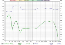
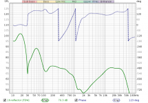
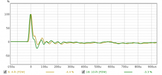
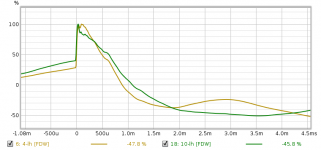
I put a poster size whiteboard behind the spark to check how similar the primary wave is to the reflection. First picture is the spectrum of the primary doublet with a 5 cycle frequency dependent window. Second picture is the reflection. The stuff under 2k is the residual LF impulse from the primary wave. Inconclusive... But I'm leaning more and more towards the LF effect being overload of something.
In my measurements I don't see obvious nulls from a bessel function. If they are there they are filled in by some other signal or they are out of my measurement BW. There are a few nulls, but not spaced at the correct intervals for a bessel function. It could just be my close up low energy sparks have a higher useful BW. However this is not as viable with other microphones that don't have very good shielding like the EM172.
Attachments
The broken equation put the frequency nulls in the wrong places, but the bessel function min and max given in the paper matched what I got from Wolfram Alpha. Once that is corrected, I can conceive that there could be errors in the matching of the <BW and >BW sections of the spectrum which are computed separately. But I am out of my depth in trying to spot any more errors.
Got the same answers too after I realized the spherical bessel function is defined in terms of the regular bessel function of order 1.5. My library does not pre-define the convenience functions. If I can find my original data I might check the fit, from the references the null frequencies are related to the pulse width so even if they are obscured the fit just before the first null should be OK by estimating the pulse width T.
Last edited:
Looks to me like you're driving both sides of the gap with the same coil, then loading both sides with the other coil ") Maybe you know something about V-6 coil packs that I don't, but all the ones I've seen drive each plug-pair with one of three coils.
Maybe you know something about V-6 coil packs that I don't, but all the ones I've seen drive each plug-pair with one of three coils.
I'd recommend a separate wire to a coil-pack mounting hole (did I see a little brass insert in one hole?) for the arc return path.
(Of course, as always, the crossed wires may just be in my brain . . It certainly wouldn't be the first time!)
Cheers
Maybe you know something about V-6 coil packs that I don't, but all the ones I've seen drive each plug-pair with one of three coils.I'd recommend a separate wire to a coil-pack mounting hole (did I see a little brass insert in one hole?) for the arc return path.
(Of course, as always, the crossed wires may just be in my brain . .
It certainly wouldn't be the first time!)Cheers
Coilpacks have 3 coils, from left to right. There are 4 inputs, one common and one separate for each of the 3 coils. What you may not see is that the alligator clip to the inputs is bridging the first and second coil inputs, so they are in parallel.
The metal mounting hole inserts aren't connected to anything, many coilpacks don't have them. Grounding the circuit may make things worse as the HV output would not longer be balanced, and this could increase electrical noise.
So in that picture the primary and secondary coils are in parallel.
The metal mounting hole inserts aren't connected to anything, many coilpacks don't have them. Grounding the circuit may make things worse as the HV output would not longer be balanced, and this could increase electrical noise.
So in that picture the primary and secondary coils are in parallel.
Last edited:
Three more interesting references:
Experimental and analytical evaluation of the acoustic radiation of femtosecond laser plasma filament sound sources in air
https://asa.scitation.org/doi/full/10.1121/1.5124509#
Laser-induced acoustic point source for accurate impulse response measurements within the audible bandwidth
https://asa.scitation.org/doi/10.1121/1.4879664
Acoustic Radiation from a Finite Line Source with N‐Wave Excitation
https://asa.scitation.org/doi/10.1121/1.1910966
Last edited:
Sorry, but if you're driving two primaries with the same signal, what you're getting out is two matching signals, not 'balanced' HV.
The common lead of the primaries should be the HV return -- purdy sher -- at least that's the way it would be used on the engine.
Forget to mention: Love the 'gators!
Cheers
The common lead of the primaries should be the HV return -- purdy sher
-- at least that's the way it would be used on the engine.Forget to mention: Love the 'gators!
Cheers
Three more interesting references:
The second one shows a more symmetrical pulse unfortunately femto-sec lasers are not DIY. I have a friend who used to work on spook stuff at DARPA and he told me about some dramatic accidents. It still appears a pulse from an electrical pulse has asymmetry such as the one in post #36.
On another point the formula from the MIT thesis is simply the analytical solution of the Fourier integral. Sampling the pulse on a fine grid (i.e. 1M points) and simply doing the FFT gives the same answer (a shrinking discrepancy with higher sampling rate here a few percent at 100kHz). I can only conclude that a reference mic is needed to determine the shape of a given generator so others can use the technique by copying the circuit exactly. I suspect if one used the universal replacement piezo grill lighter with the same gap it would be as close as one might want at least to 20kHz or so.
Attachments
Last edited:
Sorry, but if you're driving two primaries with the same signal, what you're getting out is two matching signals, not 'balanced' HV.
The common lead of the primaries should be the HV return -- purdy sher
Perhaps you should get one and then report your DMM results in finding out where the HV return is.
The output coils are isolated from the primary circuit. The output current takes an isolated path through both spark plugs from one end of the coil to the other. Well I suppose it takes a path through the engine block to get between spark plugs, but there is no such connection in this spark generator.
It is balanced whether or not I use two coils in parallel.
I first saw that trick in a Citroen 2CV. Both plugs fired at the same time with one on an exhaust stroke doing nothing. It made for a cheaper distributor, no HV parts.
What is the self resonance of that coil? That would limit its response time. I believe they are getting quite fast. Would it be possible to use an amp to drive the primary with a pulse out as a transformer for the arc?
What is the self resonance of that coil? That would limit its response time. I believe they are getting quite fast. Would it be possible to use an amp to drive the primary with a pulse out as a transformer for the arc?
It still appears a pulse from an electrical pulse has asymmetry such as the one in post #36.
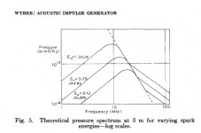
If you can get to the third reference, it uses lower energy sparks of 0.1J and 0.01J, and the resulting wave is closer to the ideal N-wave. This matches my suspicion that lower spark energy gives better BW.
I first saw that trick in a Citroen 2CV. Both plugs fired at the same time with one on an exhaust stroke doing nothing. It made for a cheaper distributor, no HV parts.
What is the self resonance of that coil? That would limit its response time. I believe they are getting quite fast. Would it be possible to use an amp to drive the primary with a pulse out as a transformer for the arc?
That is the waste spark type ignition and is used on quite a lot of V6 cars with coilpacks, mainly GM.
The resonance of the secondary of the coilpack appears to be at 250KHz. Primary resistance is 0.5ohms, secondary is 10kohm. I don't have an amp I would trust to drive this.
I found another transistor that works better for triggering due to the internal pull down resistor:
http://dalincom.ru/datasheet/BU2520DF.pdf
Sorry I didn't think of this before my last post: You could float the primary common and drive separate coils with a capacitive discharge. Providing there's no *damper* diode molded in there somewhere, that would give opposite polarity HV's.
And not only Citroen -- the inline 2-cylinder four-strokes from Japan have used a single coil/ignition system (driving both plugs every revolution) for decades.
When it comes to DMM assessments of ignition components -- so many modern parts have 5-figure resistances built into them, I usually ignore any measurement that doesn't pass a reasonable-ness test -- but that's probably just me!
Cheers
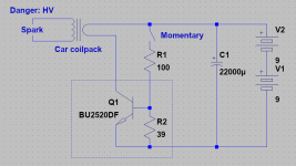
No internal diodes as far as I can see. Schematic of my setup attached.
These GM coilpacks have standard 0.5ohm and 10kohm primary/secondary resistances. (IIRC primary resistance was revised to 0.7ohm or something like that).
It will usually fire a spark on both contact and breaking. So this coil does not rely on flyback effect to generate the spark.
These GM coilpacks have standard 0.5ohm and 10kohm primary/secondary resistances. (IIRC primary resistance was revised to 0.7ohm or something like that).
It will usually fire a spark on both contact and breaking. So this coil does not rely on flyback effect to generate the spark.
Attachments
If you can get to the third reference, it uses lower energy sparks of 0.1J and 0.01J, and the resulting wave is closer to the ideal N-wave. This matches my suspicion that lower spark energy gives better BW.
I got a paywall on just that one??
Wyber found that too, the problem is that the physics of the compression and rarefaction halves of the wave are totally different and it is not possible to get a sharp edge on the cooling half. There is also the problem that extending the "flat" part of the spectrum reduces SNR. I see they went way below Wyber and I can't read how they dealt with that issue in terms of getting the mic that close to the spark, ambient noise, etc.
Attachments
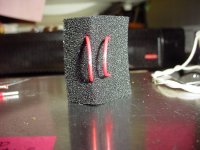
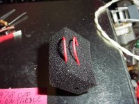
Here is the spark gap I came up with that seems to give good sparks with good consistency.
The spark fires from the sides of the wires which gives a "pointless" electrode surface with minimal obstruction or horn effect to the shockwave. The U shape of the wires seems less prone to vibration and is damped by the foam. The foam is turned so that an edge faces the shockwave to minimize reflected energy. I suppose a corner would be better in theory. I use it with the U bend pointing toward the mic.
The wires are only partially stripped where the spark fires, but it works and is more convenient. Eventually I will see if stripping it fully makes a difference. This is Teflon insulated silver plated wire, nearly impossible to strip.
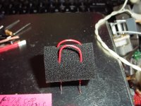
Right now I'm experimenting with U electrodes on the side of a cardboard box. The problem with a discharge near a surface is that the spark tends to jump across the cardboard. So I put electrical tape under the electrodes which helps but still about half of all sparks cling to the surface.
I also suspect that the spark is exploding dust in the air or on the surface of the cardboard which is causing the LF content which is very inconsistent.
The spark fires from the sides of the wires which gives a "pointless" electrode surface with minimal obstruction or horn effect to the shockwave. The U shape of the wires seems less prone to vibration and is damped by the foam. The foam is turned so that an edge faces the shockwave to minimize reflected energy. I suppose a corner would be better in theory. I use it with the U bend pointing toward the mic.
The wires are only partially stripped where the spark fires, but it works and is more convenient. Eventually I will see if stripping it fully makes a difference. This is Teflon insulated silver plated wire, nearly impossible to strip.
Right now I'm experimenting with U electrodes on the side of a cardboard box. The problem with a discharge near a surface is that the spark tends to jump across the cardboard. So I put electrical tape under the electrodes which helps but still about half of all sparks cling to the surface.
I also suspect that the spark is exploding dust in the air or on the surface of the cardboard which is causing the LF content which is very inconsistent.
Attachments
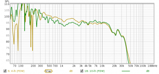
I don't trust my EM172 with time domain since it rolls off at 10k. It is also hard to aim the 10mm capsule.
I am trying the cardboard box as a baffle because it improves SNR. I am looking for the setup which minimizes the LF impulse in the doublet response. The spark generator seems to prefer a specific gap size with a specific trigger resistor to get a better chance of having a good SNR in the resulting doublets. I choose doublets which have greater difference between 10KHz and 1KHz content (should be something like 21db based on the datasheet curve). Environmental noise and the myterious LF impulse both impact SNR, so there is an advantage to finding an optimal spark and then increasing the SPL with a baffle rather than increasing mic gain or disturbing the sparker tuning. It's very specific to my rig.
Models of the edge diffraction in Edge show +-1db from 1KHz up, so I don't see the baffle as a primary source of error.
Attached is an example of a measurement with the inconsistent LF impulse (yellow) compared to one without it (green). The peaks and dips are the same, but the inconsistent LF impulse causes some of the doublets to have excessive LF response. Green is closer to the EM172 datasheet curve. There is also step response.
Floating electrodes in theory make the best point source, but the foam doesn't seem to cause any serious differences in response.
Attachments
- Home
- Design & Build
- Equipment & Tools
- Spark calibration of microphones