UPL Serial Number and Option Codes
First of all, I would like to thank Bart for his fantastic work, well done!
I appreciate the generous supply of information and files. It helped me figure out a simple way to unlock options without knowing the algorithm, something I wanted to do for years. Of course with a Logic Analyzer and a Disassembler you can crack the code but it is a very tedious job and takes a LONG time.
I want to sum up in one post how to change the serial number to a UPL with known Option Codes.
Bart provided these but you can find them also on Ebay looking at the rear panel pics of UPLs for sale.
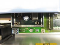
To make changing the serial EEPROM data easier I desoldered the EEPROM on the Analog Board and mounted a 8 pin DIL socket in the corner of the board near the SMD EEPROM (see pic). I resoldered the EEPROM on an adapter board (sold on Ebay, intended for use with OP-Amps, but working just fine with the EEPROM). I made two of those, so it was simple to swap and program the EEPROM. Of course you can also use Bart's approach with the SOIC test clip.
The Serial number for newer models consists of two parts (see also Operation Manual 1.2 Fitting Options):
1. Serial Number xxxxxx
2. Material Number 1078.2008Kxx
In the Options/Diagnostic menu the Serial number is located at Address 0, the 2 digit part of the Material Number at Address 1.The number of the Analog Board is located at Address 2 (you do not need that). The value at Address 3 is 0. I am not sure what that is but you do not need it either.
To dig deeper and access the cal data, enter one of the 2 working passwords: serviceRuS or 1.4142.
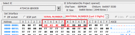
In the serial EEPROM the Serial Number is saved as "int32" at bytes 4-7, the 2 digit part of the Material Number at bytes 8-11. The format is Intel Little Endian Byte Order.
The easiest way for me was to read the EEPROM via a programmer, change the Serial Number (6 and 2 digit parts) in a Hex Editor (I use HexWorkshop but any other Hex editor will also work) and rewrite the EEPROM. The UPL will then write the new Serial number to the HDD at startup. FYI, The files SERIAL.NR, INSTKEY.NR and several *.CAL files are located under UPL/REF. The *.CAL files will not be altered.
Another way would be to erase the EEPROM and type in the new Serial Number at the UPL (It will let you do it only if the EEPROM was erased; this is the production scenario with a fresh UPL) but then you will have to restore the calibration data (which is stored in the EEPROM and on HDD as backup). I did not do it that way.
After having changed the Serial Number you can type in the Option Codes that are tied to the new Serial Number. That's it. Again: do not forget to change both Serial Number (Address 0) and the 2 digit part of the Material Number (Address 1).
The procedure might be a bit different with older models that do not have the Material Number (see again Operation Manual 1.2 Fitting Options). I did not try that because I do not have an older UPL at my hands.
Good luck!
One last mention: I installed a network card on my UPL (being the server) under DOS. File access is fine with WinXP and Win7 (only via mapped network drive, in the network explorer you can see the UPL but you cannot access it). At first I could also access the files from Win10 but after some Win10 security updates in 2020 that does not work anymore. It is a known issue. I consider it not worth the while to find a workaround. I will use Win7 or WinXP for access.
Best regards!
First of all, I would like to thank Bart for his fantastic work, well done!
I appreciate the generous supply of information and files. It helped me figure out a simple way to unlock options without knowing the algorithm, something I wanted to do for years. Of course with a Logic Analyzer and a Disassembler you can crack the code but it is a very tedious job and takes a LONG time.
I want to sum up in one post how to change the serial number to a UPL with known Option Codes.
Bart provided these but you can find them also on Ebay looking at the rear panel pics of UPLs for sale.
To make changing the serial EEPROM data easier I desoldered the EEPROM on the Analog Board and mounted a 8 pin DIL socket in the corner of the board near the SMD EEPROM (see pic). I resoldered the EEPROM on an adapter board (sold on Ebay, intended for use with OP-Amps, but working just fine with the EEPROM). I made two of those, so it was simple to swap and program the EEPROM. Of course you can also use Bart's approach with the SOIC test clip.
The Serial number for newer models consists of two parts (see also Operation Manual 1.2 Fitting Options):
1. Serial Number xxxxxx
2. Material Number 1078.2008Kxx
In the Options/Diagnostic menu the Serial number is located at Address 0, the 2 digit part of the Material Number at Address 1.The number of the Analog Board is located at Address 2 (you do not need that). The value at Address 3 is 0. I am not sure what that is but you do not need it either.
To dig deeper and access the cal data, enter one of the 2 working passwords: serviceRuS or 1.4142.
In the serial EEPROM the Serial Number is saved as "int32" at bytes 4-7, the 2 digit part of the Material Number at bytes 8-11. The format is Intel Little Endian Byte Order.
The easiest way for me was to read the EEPROM via a programmer, change the Serial Number (6 and 2 digit parts) in a Hex Editor (I use HexWorkshop but any other Hex editor will also work) and rewrite the EEPROM. The UPL will then write the new Serial number to the HDD at startup. FYI, The files SERIAL.NR, INSTKEY.NR and several *.CAL files are located under UPL/REF. The *.CAL files will not be altered.
Another way would be to erase the EEPROM and type in the new Serial Number at the UPL (It will let you do it only if the EEPROM was erased; this is the production scenario with a fresh UPL) but then you will have to restore the calibration data (which is stored in the EEPROM and on HDD as backup). I did not do it that way.
After having changed the Serial Number you can type in the Option Codes that are tied to the new Serial Number. That's it. Again: do not forget to change both Serial Number (Address 0) and the 2 digit part of the Material Number (Address 1).
The procedure might be a bit different with older models that do not have the Material Number (see again Operation Manual 1.2 Fitting Options). I did not try that because I do not have an older UPL at my hands.
Good luck!
One last mention: I installed a network card on my UPL (being the server) under DOS. File access is fine with WinXP and Win7 (only via mapped network drive, in the network explorer you can see the UPL but you cannot access it). At first I could also access the files from Win10 but after some Win10 security updates in 2020 that does not work anymore. It is a known issue. I consider it not worth the while to find a workaround. I will use Win7 or WinXP for access.
Best regards!
Attachments
First of all, I would like to thank Bart for his fantastic work, well done!
I appreciate the generous supply of information and files. It helped me figure out a simple way to unlock options without knowing the algorithm, something I wanted to do for years. Of course with a Logic Analyzer and a Disassembler you can crack the code but it is a very tedious job and takes a LONG time.
I want to sum up in one post how to change the serial number to a UPL with known Option Codes.
Bart provided these but you can find them also on Ebay looking at the rear panel pics of UPLs for sale.
To make changing the serial EEPROM data easier I desoldered the EEPROM on the Analog Board and mounted a 8 pin DIL socket in the corner of the board near the SMD EEPROM (see pic). I resoldered the EEPROM on an adapter board (sold on Ebay, intended for use with OP-Amps, but working just fine with the EEPROM). I made two of those, so it was simple to swap and program the EEPROM. Of course you can also use Bart's approach with the SOIC test clip.
The Serial number for newer models consists of two parts (see also Operation Manual 1.2 Fitting Options):
1. Serial Number xxxxxx
2. Material Number 1078.2008Kxx
In the Options/Diagnostic menu the Serial number is located at Address 0, the 2 digit part of the Material Number at Address 1.The number of the Analog Board is located at Address 2 (you do not need that). The value at Address 3 is 0. I am not sure what that is but you do not need it either.
To dig deeper and access the cal data, enter one of the 2 working passwords: serviceRuS or 1.4142.
In the serial EEPROM the Serial Number is saved as "int32" at bytes 4-7, the 2 digit part of the Material Number at bytes 8-11. The format is Intel Little Endian Byte Order.
The easiest way for me was to read the EEPROM via a programmer, change the Serial Number (6 and 2 digit parts) in a Hex Editor (I use HexWorkshop but any other Hex editor will also work) and rewrite the EEPROM. The UPL will then write the new Serial number to the HDD at startup. FYI, The files SERIAL.NR, INSTKEY.NR and several *.CAL files are located under UPL/REF. The *.CAL files will not be altered.
Another way would be to erase the EEPROM and type in the new Serial Number at the UPL (It will let you do it only if the EEPROM was erased; this is the production scenario with a fresh UPL) but then you will have to restore the calibration data (which is stored in the EEPROM and on HDD as backup). I did not do it that way.
After having changed the Serial Number you can type in the Option Codes that are tied to the new Serial Number. That's it. Again: do not forget to change both Serial Number (Address 0) and the 2 digit part of the Material Number (Address 1).
The procedure might be a bit different with older models that do not have the Material Number (see again Operation Manual 1.2 Fitting Options). I did not try that because I do not have an older UPL at my hands.
Good luck!
One last mention: I installed a network card on my UPL (being the server) under DOS. File access is fine with WinXP and Win7 (only via mapped network drive, in the network explorer you can see the UPL but you cannot access it). At first I could also access the files from Win10 but after some Win10 security updates in 2020 that does not work anymore. It is a known issue. I consider it not worth the while to find a workaround. I will use Win7 or WinXP for access.
Best regards!
Thanks! you really took my EEPROM problem and twisted it to your advantage. Nice job! And thanks for sharing it here!
I'm now running win98 on my UPL with a mapped drive to my NAS. I can quickly take screenshots and export measurement data directly over the network. Another nice feature of this is that when you press printscreen on the keyboard you can easily minimize the UPL program and open paint and save your screenshot there. I'm really enjoying this setup. DOS is nice but this was really the missing link in my workflow.
Cheers,
Bart
KeyBoard Repair Follow up
Hi,
I got some questions on the UPL Keyboard layout so I thought I would simply share my github link here.
Enjoy!
GitHub - bvksound/UPL_AudioAnalyzer
Cheers,
Bart
Hi,
I got some questions on the UPL Keyboard layout so I thought I would simply share my github link here.
Enjoy!
GitHub - bvksound/UPL_AudioAnalyzer
Cheers,
Bart
UPL ethernet client
I use FileZilla in my UPL FTP server project. FileZilla PC client works well also under W10.
FileZilla - The free FTP solution
Link to my old UPL Ethernet project.
https://www.diyaudio.com/forums/equ...acklight-rohde-schwarz-upl-4.html#post5043393
I use FileZilla in my UPL FTP server project. FileZilla PC client works well also under W10.
FileZilla - The free FTP solution
Link to my old UPL Ethernet project.
https://www.diyaudio.com/forums/equ...acklight-rohde-schwarz-upl-4.html#post5043393
ISA Interconnect PCB
Hi All,
Had some time and figured I would make a PCB design for the ISA Interconnect board. This small PCB connects the PC Motherboard to the Main Digital Board.
Gerber files can be found in my github. Let me know if there is some interest, I might have them made.
GitHub - bvksound/UPL_AudioAnalyzer
PCB Design.png - Google Drive
Cheers,
Bart
Unlock UPL Options (EEPROM Hack)
Hi,
Thanks to the help of mgams, the unlocking of options for the UPL becomes super easy. I thought I'd summarize it here with some more details.
The concept is that instead of searching endlessly for the algorithm to generate install keys, you flash your EEPROM with my serial number (828288/02) from which I have all possible install keys!
Disclaimer: This should be done at your own risk, make sure you have a backup of your EEPROM before modifying anything. By doing this hack, the UPL will invalidate all existing keys that were on your unit since the Serial Number does not match anymore. After this you can enter new keys listed below.
Tools:
TL866II+ Mini Pro USB Universal Nand Spi eeprom Programmer | eBay
Test CLIP SOIC 8 SOP8 ESP8266 ICS BIOS/24/25/93 AVR Programmer Clip Adapter... | eBay
The clip is what you need if you don't want to solder the fragile board. It works perfectly for me.
The EEPROM chip is an AT24C164 from ATMEL and is located on the analog board.
Steps:
The list of possible keys can be found here:
sn:828288/2 opt:0 key:58090 // UPL-B4 1078.3804.02 Remote Control (manual enabling)
sn:828288/2 opt:1 key:38173 // UPL-B21 1078.3856.02 Digital Audio Protocol (manual enabling)
sn:828288/2 opt:2 key:31475 // UPL-B22 1078.3956.02 Jitter and Interface Test (manual enabling)
sn:828288/2 opt:3 key:58670 // UPL-B10 1078.3904.02 Universal Sequence Controller (manual enabling)
sn:828288/2 opt:4 key:55957 // UPL-B6 1078.4500.02 Extended Analysis Functions (manual enabling)
sn:828288/2 opt:5 key:58851 // UPL-B33 1078.4852.02 Line Measurement to ITU-T O.33 (manual enabling)
sn:828288/2 opt:6 key:56079 // UPL-B8 1117.3505.02 Mobile Phone Test Set (automatic installation)
sn:828288/2 opt:7 key:59095 // UPL-B23 1078.5188.02 Coded Audio Signal Generation (automatic installation)
sn:828288/2 opt:8 key:56679 // UPL-B9 1154.7500.02 3G Mobile Phone Tests (automatic installation)
sn:828288/2 opt:9 key:43527 // UPL-B81 1154.7900.02 UPL16 UPGRADE DAI TESTS REL99 WITH CMU
Cheers!
Bart
Hi,
Thanks to the help of mgams, the unlocking of options for the UPL becomes super easy. I thought I'd summarize it here with some more details.
The concept is that instead of searching endlessly for the algorithm to generate install keys, you flash your EEPROM with my serial number (828288/02) from which I have all possible install keys!
Disclaimer: This should be done at your own risk, make sure you have a backup of your EEPROM before modifying anything. By doing this hack, the UPL will invalidate all existing keys that were on your unit since the Serial Number does not match anymore. After this you can enter new keys listed below.
Tools:
TL866II+ Mini Pro USB Universal Nand Spi eeprom Programmer | eBay
Test CLIP SOIC 8 SOP8 ESP8266 ICS BIOS/24/25/93 AVR Programmer Clip Adapter... | eBay
The clip is what you need if you don't want to solder the fragile board. It works perfectly for me.
The EEPROM chip is an AT24C164 from ATMEL and is located on the analog board.
Steps:
- Unplug all flatcables from the analog board
- Fix the clip on the eeprom. Watch out for pin1 orientation
- Read the EEPROM
- Save the EEPROM file as a backup
- Modify Byte 4-7 with the Serial Number 80 A3 0C 00
- Modify Byte 8-11 with the Material Number 02 00 00 00
- Write the modified contents back to the EEPROM
- Disconnect the programmer clip
- Reconnect the flatcables on the Analog Board
- Start up the UPL Unit
- Confirm any messages during the load screen (You want to save whatever is on the Analog board to the HDD)
- Enter the keys needed in the Options menu
The list of possible keys can be found here:
sn:828288/2 opt:0 key:58090 // UPL-B4 1078.3804.02 Remote Control (manual enabling)
sn:828288/2 opt:1 key:38173 // UPL-B21 1078.3856.02 Digital Audio Protocol (manual enabling)
sn:828288/2 opt:2 key:31475 // UPL-B22 1078.3956.02 Jitter and Interface Test (manual enabling)
sn:828288/2 opt:3 key:58670 // UPL-B10 1078.3904.02 Universal Sequence Controller (manual enabling)
sn:828288/2 opt:4 key:55957 // UPL-B6 1078.4500.02 Extended Analysis Functions (manual enabling)
sn:828288/2 opt:5 key:58851 // UPL-B33 1078.4852.02 Line Measurement to ITU-T O.33 (manual enabling)
sn:828288/2 opt:6 key:56079 // UPL-B8 1117.3505.02 Mobile Phone Test Set (automatic installation)
sn:828288/2 opt:7 key:59095 // UPL-B23 1078.5188.02 Coded Audio Signal Generation (automatic installation)
sn:828288/2 opt:8 key:56679 // UPL-B9 1154.7500.02 3G Mobile Phone Tests (automatic installation)
sn:828288/2 opt:9 key:43527 // UPL-B81 1154.7900.02 UPL16 UPGRADE DAI TESTS REL99 WITH CMU
Cheers!
Bart
Attachments
Last edited:
Mobile phone tests require a separate board.
Comes preinstalled in UPL16
You're right, some digital options will also only work with dedicated hardware installed in the UPL.
TBH, I am not sure it has a positive effect having all those modules loaded.
Without specific HW it doesn't make any sense, on a standard model B4,B6 and B10 are possible.
But it's good to have if you can score a HW Module somewhere.
Rohde & Schwarz UPL Analyzer Revisions
Hi,
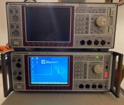
Recently I had another UPL with screen in for repair. However there were some changes compared to mine.
This was a good opportunity to see the differences.
My unit:
visually distinguishable by the straight lines from the function keys.
LCD Panel: Toshiba LTM08C015K 8.4" 640*480 TFT LCD Panel
The other unit (according to me newer)
visually distinguishable by the angled lines from the function keys. The screen cutout seems larger.
LCD Panel: SHARP LQ084V1DG21 8.4" 640*480 TFT LCD Panel + has a control board of R&S on the back of the screen assembly that then interfaces with the digital board.
There are alternative types listed in the service manual as well but these are the ones physically inside the units.
I've also noticed that all my documentation (service manuals) are for my unit/revision. Even though many items have not been changed, screen and front panel do seem to be different.
This was also a good opportunity to disassemble the original keyboard and take some measurements + compare it to my PCB.
The keyboard panels are the same in all revisions as far as I see. More pictures can be found here.
KeyBoard - Google Drive
All the best,
Bart
Hi,
Recently I had another UPL with screen in for repair. However there were some changes compared to mine.
This was a good opportunity to see the differences.
My unit:
visually distinguishable by the straight lines from the function keys.
LCD Panel: Toshiba LTM08C015K 8.4" 640*480 TFT LCD Panel
The other unit (according to me newer)
visually distinguishable by the angled lines from the function keys. The screen cutout seems larger.
LCD Panel: SHARP LQ084V1DG21 8.4" 640*480 TFT LCD Panel + has a control board of R&S on the back of the screen assembly that then interfaces with the digital board.
There are alternative types listed in the service manual as well but these are the ones physically inside the units.
I've also noticed that all my documentation (service manuals) are for my unit/revision. Even though many items have not been changed, screen and front panel do seem to be different.
This was also a good opportunity to disassemble the original keyboard and take some measurements + compare it to my PCB.
The keyboard panels are the same in all revisions as far as I see. More pictures can be found here.
KeyBoard - Google Drive
All the best,
Bart
Attachments
Most of the revisions are due to the parts discontinuation.
Some motherboards have socketed ICs on the DSP board. This is because the original ones were NLA and R&S had to make it work somehow.
Last production date for the UPL is 2003-2004.
UPV came after, which will be discontinued in a couple of years as some components inside are NLA as well.
PS. Some UPL have the jog wheel with a press function. Others do not.
For example the ADC is NLA. They have stocks, but a diagnose & repair & calibration will cost more than a 2nd hand unit.
It is unofficial. Simply crosschecked major components and some of them are discontinued.
Also no major SW updates for some time.
Same as the UPL.
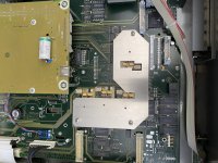
I have come across a unit UPL66 that seems to have a adapter-board for certain chips. as far as I can see the digital board is unchanged but certain chips have been replaced by sockets and an adapter-board is fitted on top.
PS: The botched battery replacement is not my work. That had to go and an original matching battery was fitted!
Attachments
- Home
- Design & Build
- Equipment & Tools
- Rohde Schwarz R&S UPL Audio Analyzer Renovation