Hi guys,
I'm in the process of making a toroidal winder, and thought there might be an interest is seeing all of my mistakes.. btw, I'm using scrap parts from my bin for most of this. I will drive it with an arduino.
I see three types out there.
Belt type, shuttle type, and two ring gear driven style. Given the nature of the toroids and accuracies we need, I chose to make the two ring type.
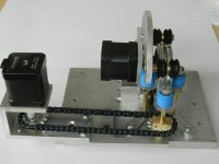
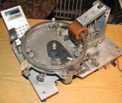
Here is an overall picture of the present design.
The motors are nema 17 steppers. The center one drives the left ring, the left one turns the toroid.
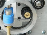
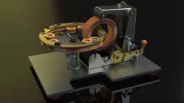
Second pic shows the ring drive up close. I decided to do inner drive, the ring teeth are actually a belt cut to length, I turned the inner ring surface to an ID for a specific belt length.
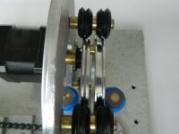
The third pic shows the two rings. Left has the pully that will guide the wire down to the toroid, the right will have all the wire spooled onto it.
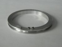
The fourth is the right hand ring, a work in progress. the screws are 1-72, they will hold the hinge plate so I can split the ring to put the toroid in. The slot is .018 inches deep, the steel thickness I have.
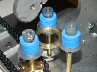
The fifth pic shows how the toroid is supported. The blue is sticky back foam of the type used for kids stickers. It is too soft, so when the toroid direction reverses, the toroid walks sideways a bit.
The chain drive to turn the toroid I do not like, I will be modding that into a direct drive with the motor underneath. The sprockets do not have perfect root to center distances, and the chain alternates between tight and ok. Also, the chain does not like to disengage as it rotates, causing a slight cogging.
I want to microstep the motor for finer resolution, right now, it is about 400 counts per toroid turn.
The blue foam, I will be replacing with latex rubber surgical tubing. I think one layer will suffice. I may have to turn the acrylic flange down, as it will go too far into the toroid with a thin tube surface.
Oh, the foam/rubber is to give a compliant surface that turns the toroid, but does not get in the way of the wire already wound.
jn
I'm in the process of making a toroidal winder, and thought there might be an interest is seeing all of my mistakes.. btw, I'm using scrap parts from my bin for most of this. I will drive it with an arduino.
I see three types out there.
Belt type, shuttle type, and two ring gear driven style. Given the nature of the toroids and accuracies we need, I chose to make the two ring type.
Here is an overall picture of the present design.
The motors are nema 17 steppers. The center one drives the left ring, the left one turns the toroid.
Second pic shows the ring drive up close. I decided to do inner drive, the ring teeth are actually a belt cut to length, I turned the inner ring surface to an ID for a specific belt length.
The third pic shows the two rings. Left has the pully that will guide the wire down to the toroid, the right will have all the wire spooled onto it.
The fourth is the right hand ring, a work in progress. the screws are 1-72, they will hold the hinge plate so I can split the ring to put the toroid in. The slot is .018 inches deep, the steel thickness I have.
The fifth pic shows how the toroid is supported. The blue is sticky back foam of the type used for kids stickers. It is too soft, so when the toroid direction reverses, the toroid walks sideways a bit.
The chain drive to turn the toroid I do not like, I will be modding that into a direct drive with the motor underneath. The sprockets do not have perfect root to center distances, and the chain alternates between tight and ok. Also, the chain does not like to disengage as it rotates, causing a slight cogging.
I want to microstep the motor for finer resolution, right now, it is about 400 counts per toroid turn.
The blue foam, I will be replacing with latex rubber surgical tubing. I think one layer will suffice. I may have to turn the acrylic flange down, as it will go too far into the toroid with a thin tube surface.
Oh, the foam/rubber is to give a compliant surface that turns the toroid, but does not get in the way of the wire already wound.
jn
Attachments
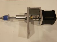
Lost the chain drive, used that u shaped section over, now there is a hardened steel shaft in place of the brass. It still binds a little bit, but really much better than the chain. I re-used an aluminum two bearing mount from an old project
Tomorrow I will order an Oldham coupler from McMaster Carr. Needs a 5mm end and an 8mm. Will end up around 30 bucks. It will be the most expensive part of the build to date.
Didn't mount it tonight, but will post pic tomorrow of the assembly.
Don't know how to post a video, but when I get it working, I will post stills of the entire operation. The internet vids kinda show, but they end up going too fast. My plan is to use the arduino and go really slow for a vid.
Jn
Ps. I'm turning parts to about .0005 inches tolerance (12.5 microns), but that darn coupler still gives issues. I suspect the coupler does not have perfectly aligned holes, and when I tighten the setscrews, it slightly misaligned the coupler. Cheap is not necessarily best, go figure.
Last edited:
What about the rubber drive belt used on basic 3D printers? I am always surprised how precise it is on Y axis (moving the heavy tray with the print-out 100mm/s), considering it is elastic.
I have only bad experience with those coil couplers. IMO loading them radially makes them bend as they rotate. Also I do not trust their precision since at initial torque they can unwind slightly, not transferring the angular move correctly.
As of arduino - the AccelStepper library is very good for moving heavier items as it handles smooth accelleration/decelleration nicely.
I played with the dirt-cheap A4988-based stepper controllers, very easy to interface with AccelStepper and handle microstepping internally. Though I ended up with geared steppers instead of microstepping.
I was definitely thinking rubber belt as well. Having seen the vids of other winders, I decided putting it direct drive with motor under give a clearer work area as well as no chain to pinch fingers.What about the rubber drive belt used on basic 3D printers? I am always surprised how precise it is on Y axis (moving the heavy tray with the print-out 100mm/s), considering it is elastic.
I have only bad experience with those coil couplers. IMO loading them radially makes them bend as they rotate. Also I do not trust their precision since at initial torque they can unwind slightly, not transferring the angular move correctly.
As of arduino - the AccelStepper library is very good for moving heavier items as it handles smooth accelleration/decelleration nicely.
I played with the dirt-cheap A4988-based stepper controllers, very easy to interface with AccelStepper and handle microstepping internally. Though I ended up with geared steppers instead of microstepping.
Thanks for the pointer, I will check out the library.
My plan is to ratio the drives for consistent wire lay and have either a 10 turn pot or rotary encoder for velocity control.
Four software modes.
1. Rotate ring CW, toroid off, display shows feet of wire spooling on. Rings coupled.
2. Rotate ring CCW, toroid slaved and geared, rings detached. Display reads total turns.
If I micro step both at 32, resolution for ratio will be great. I don't expect toroid motion to be 32 micro step accurate, as I'm running open loop.
3. Set the ratio.
4. Rotate toroid without winding motor moving.
Ps..just realized modes 3 and 4 are useful.
I can just add a selector switch to control mode. Using four digital inputs
Jn
Last edited:
Nothing beats direct drive, that's for sure ")
Unless missing steps, steppers are very reliable in terms of exact position. You may not need any feedback (perhaps only some reset for initial position, do not know)
Nema 17s are pretty strong and handle microstepping nice. They are in my entry-level 3D printer (like in most other printers) and I do not remember any missed steps, with prints taking even whole day.
Here's the newer direct drive for the toroid turning. That aluminum cylindrical part has two sealed bearings, one either end.
the shaft is hardened steel. Needed the cutoff wheel to trim it down to length.
Tomorrow and the weekend, I put it together and work on finishing the rings.
jn
the shaft is hardened steel. Needed the cutoff wheel to trim it down to length.
Tomorrow and the weekend, I put it together and work on finishing the rings.
jn
Attachments
I tried to build toroidal winder back in 2013. It was semi-working prototype without roller calmp table for toroidal core (so I used boxes and books, and rotated core manually to determine if this costruction is workable). The external diameter of wire spool and shuttle is about 355mm (~ 14 inch). I abandoned this project because of the too high cost.
Pictures attached. So you can take some lessons from my achievements and mistakes.
Pictures attached. So you can take some lessons from my achievements and mistakes.
Attachments
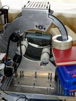
Wow, very nice work. I note you were setting up the second ring to be driven as well.I tried to build toroidal winder back in 2013. It was semi-working prototype without roller calmp table for toroidal core (so I used boxes and books, and rotated core manually to determine if this costruction is workable). The external diameter of wire spool and shuttle is about 355mm (~ 14 inch). I abandoned this project because of the too high cost.
Pictures attached. So you can take some lessons from my achievements and mistakes.
The vid I saw has only one drive, so I went that route. But man, that was certainly an ambitious project, it looked quite good. I'm glad you kept pictures.
John
Last edited:
How's the tension control going to be on this. In other words, how small of wire can you go?
Cheers
Alan
The engineer who will use it wanted 28 to 30 awg.
My current plan is to make a felt pad brake that touches the inner surface of the wire spool ring and adjust it with springs.
The only unknown for me is, as the pully of the first ring heads back towards the toroid, I want to make sure that the tension on the wire remains the same. From the video i studied, the loaded ring slows down a lot during that portion of the wind, but I do not think it will need to back up to maintain tension. In the video, the thick wire did tend to loop up just before the pully, but I suspect it was because the wire is so thick and the pully radius is so small that the wire fights the bend.
If it does, I will have to make a floating brake with a spring so that if it needs to back up, the spring will do that. But until I see a need to add that complexity, I will refrain (however, keeping it in mind.)
john
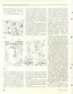
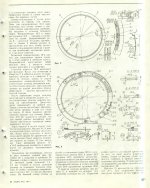
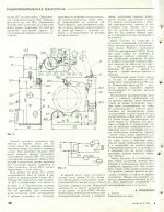
I draw my inspiration from an article published in Russian "Radio" magazine back in 1987. It included complete set of drawing of all parts necessary to build machinery. However, I decided for more classic build with vertical spool bobbin and shuttle.
Attachments
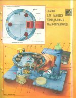
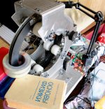
Someone has build an actual machine (on the photo of unknown origin from Russia).
Additionally, there is a complete SolidWorks model on GrabCad, so you can take all data and build.
Free CAD Designs, Files & 3D Models | The GrabCAD Community Library
Additionally, there is a complete SolidWorks model on GrabCad, so you can take all data and build.
Free CAD Designs, Files & 3D Models | The GrabCAD Community Library
Attachments
The first pic, wow, it looks like it's been out in the weather for a few years.
It shows the wire exactly where I was concerned about wire tension. As the pulley moves toward the toroid, it's actually rolling on the wire towards the toroid.. I believe the source spool almost stops, but doesn't have to back up. That's the question for now.
linuksguru, great posts and information, thank you.
From the magazine, the rings appear to be split in half. Not a bad idea. But since my rollers are OD, I think I have to keep the opening segment under 60 to 90 degrees of the ring circumference. If I build a second one, holding the rings at ID might be the choice.
BTW, while I personally don't need any toroids, this is a really fun project...and gives me great excuses to buy more tools.
ps..I may go back to the old blowtorch thread to find the core information for the RF bridge so I can build one. Such a fascinating piece of equipment.
jn
Last edited:
It shows the wire exactly where I was concerned about wire tension. As the pulley moves toward the toroid, it's actually rolling on the wire towards the toroid.. I believe the source spool almost stops, but doesn't have to back up. That's the question for now.
linuksguru, great posts and information, thank you.
jn
Wire spool bobbin rotates with variable speed, but not backward.
Last time I looked at photos of a home made toroidal winder it was based on a pushbike wheel with the spokes and hub removed and cut so that a small bit could be removed.
The removable bit also operated the turns counter and core rotator with some kind of pip on one of the fixing screws.
It was driven by a simple rubber roller.
The removable bit also operated the turns counter and core rotator with some kind of pip on one of the fixing screws.
It was driven by a simple rubber roller.
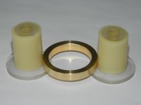
Received the surgical tubing from McMaster-Carr, they are amazing with their next day shipping.
I put the half inch ID tube on two of the toroid support parts. That blue foamy stuff was driving me nuts.
I think this tubing is going to be perfect.
Oh, the brass ring is a size duplicate to the high mu toroid we will be winding. I didn't want to compromise one of the real parts.
jn
I put the half inch ID tube on two of the toroid support parts. That blue foamy stuff was driving me nuts.
I think this tubing is going to be perfect.
Oh, the brass ring is a size duplicate to the high mu toroid we will be winding. I didn't want to compromise one of the real parts.
jn
Attachments
- Status
- This old topic is closed. If you want to reopen this topic, contact a moderator using the "Report Post" button.
- Home
- Design & Build
- Equipment & Tools
- Toroidal winding machine build