Nice to see that you built this up and tried it. Thanks for your observations. I'd love to see how this works when you get really good op amps into the circuit.
You're welcome. I only have four LM6171 around, but I imagine those 3.6kV/s monsters to become a real nightmare, once they're spread out on perfboard. Won't test that out...
I've been looking for some opamps with higher than 36V supply, but there are not that many around. LT1028 can run on 44V, but I only have two of them, and with over ten bucks a pop they're not exactly cheap. Maybe something like TLE2144A (44V) or ADA4522-4 (55V) will do; being quad opamps makes things easy, but I'll have to acquire some of those with my next order.
Have you simulated it and the active twin T to understand the noise performance differences between the two circuits?
Yes, I've played a lot with both simulations. One way to lower the noise is to use bigger capacitors and lower resistors. This works for both topologies, but only within margins of course. The SV does always outperform the TT though, as it seems.
The SV is pretty versatile with its parameters. You can actually trade some of the opamp-eating performance for worse noise and lower Q. I'll play around with my prototype to see the implications in the real world. After all, a low noise floor is not very useful if the harmonics are so high already that they never fall below it...
You're welcome. I only have four LM6171 around, but I imagine those 3.6kV/s monsters to become a real nightmare, once they're spread out on perfboard. Won't test that out...
I've been looking for some opamps with higher than 36V supply, but there are not that many around. LT1028 can run on 44V, but I only have two of them, and with over ten bucks a pop they're not exactly cheap. Maybe something like TLE2144A (44V) or ADA4522-4 (55V) will do; being quad opamps makes things easy, but I'll have to acquire some of those with my next order.
Yes, I've played a lot with both simulations. One way to lower the noise is to use bigger capacitors and lower resistors. This works for both topologies, but only within margins of course. The SV does always outperform the TT though, as it seems.
The SV is pretty versatile with its parameters. You can actually trade some of the opamp-eating performance for worse noise and lower Q. I'll play around with my prototype to see the implications in the real world. After all, a low noise floor is not very useful if the harmonics are so high already that they never fall below it...
Even if you tried a 5534 that would give you a good picture of performance with a low-noise, low distortion wideband op amp. Or even OPA604 or OPA2134 or LM4562 duals. Even though it is quite old, the 5534 still gives very good performance in instrumentation applications. Just remember that it needs a 22pF comp cap for unity gain situations like integrators.
I always prefer state variable implementations where they are appropriate. The ease of tunability and control of Q is hard to beat.
Cheers,
Bob
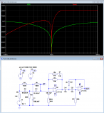
Amazing little circuit...! Let me tell you what I have found out so far. Here's the schematic again:
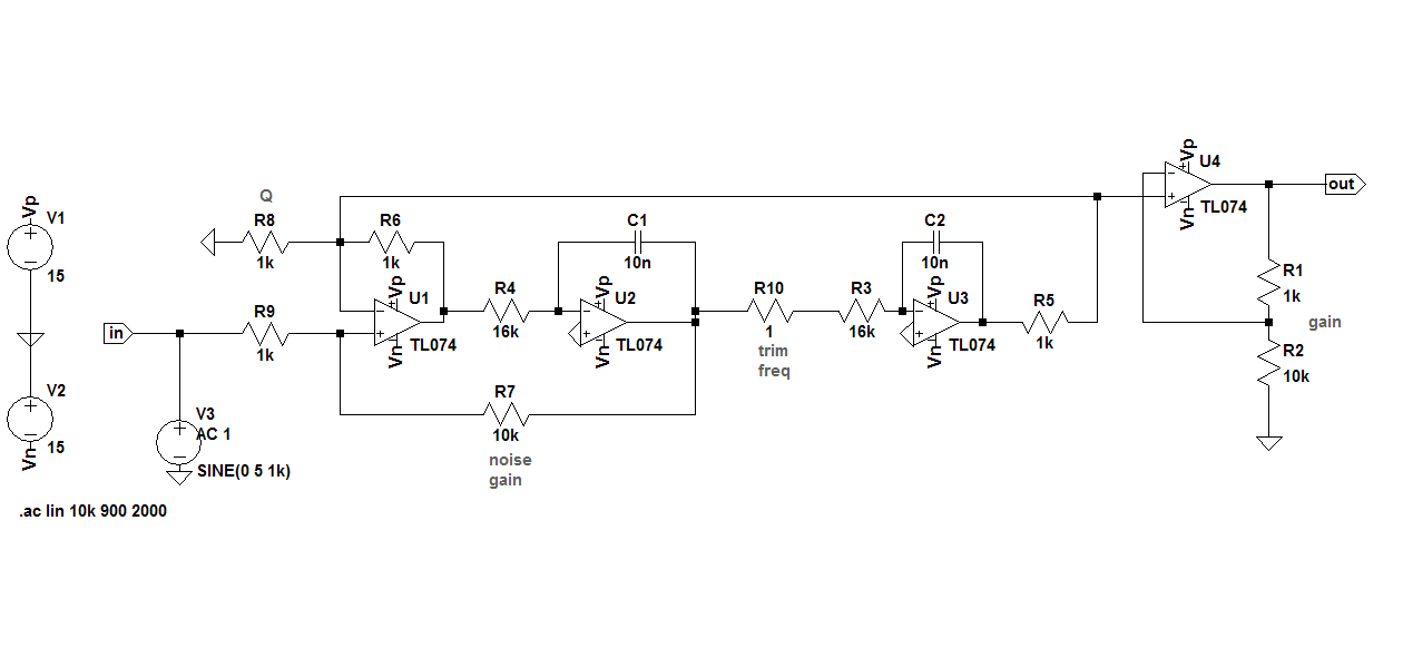
R7 and R9 set the gain for the first stage (20dB in this case) and dictate most of the performance of the whole circuit. Increasing R7 will yield a better noise performance and a higher Q (i.e. sharper and deeper notch), but will demand more performance and headroom from the opamp. The input signal will be amplified by this amount and the opamp must not clip to the rails or add distortion due to being operated too close to the rails. Decreasing R7 on the other hand makes the noise performance worse (in my sim it dropped from ~20nV with 10k/1k to ~40nV with 1k/1k) and lowers the Q, so the notch gets wider and the harmonics will be attenuated more, but now there's not such a high signal level to be handled by the opamps. I have made R7 and R9 equal with great results, which I'll show you in a minute.
R1 and R2 usually have the same ratio as R7 and R9, to make up for any gain or loss in the pass band and make the overall filter response 0dB. Of course this last stage can also be set to a higher level, to amplify the remaining distortion products.
C1/R4 and C2/R3 determine the notch frequency. The capacitors should be close in value, because a huge difference degrades the notch depth, but fortunately they don't have to be matched nearly as close as in a Twin-T! The resistors don't have to be matched at all, because one of them will be adjustable to center the notch frequency on the oscillator. You really only need that one potentiometer!
Increasing R8 will increase Q to some extent. This may be helpful for some, but I've left this pretty much unchanged.
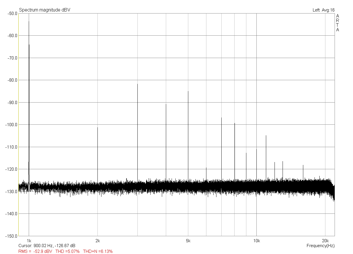
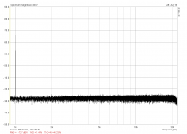
Now for some practical results. Here is the circuit from above fed with Victor's oscillator set to its lowest output level, which measured to 0.2Vrms:

You can see a lot of harmonics, which I suppose are not originating from the oscillator itself. I rather think they're produced in the first three opamp stages, which are working with 2Vrms signal level into "roughly 1k" impedance. Like I said before, the TL074 (or TL084 actually) is probably not the best choice in this case, but it was the only thing I had conveniently handy. But let's see if we can do better.

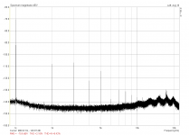
This is the result with R7 and R9 both set to 1k. This makes the gain in the first stage 0dB and thus the opamp doesn't have to work so hard anymore. You can see that the noise floor rose by about 5dB, but now you can't see no harmonics anymore! Where are they gone? The simulation of this circuit will tell us that the 2nd harmonic will be down by 3dB and the 3rd by about 1dB, due to the lowered Q of the filter, but that's certainly not enough to hide the 30+dB that we saw before. Let's try another thing:

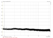
Now I have additionally changed R1 and R2 to 20k and 1k, respectively. This gives us another ~20dB gain of the signal we've seen before. We can easily check that with the indicated RMS value of the fundamental, which rose from -91.2dBV to now -72.7dBV. In the meantime between the two measurements the oscillator drifted a little and the notch was not spot-on for both, that's why we only see 18.5dB here, but that's not really important now.
The noise floor made another huge leap from below -140dB to just above -130dB, which was to be expected, but notice that there are still no harmonics to be seen!
And finally, here's Victor's oscillator with its full output of slightly more than 2Vrms into the filter. Now we've got our harmonics back, but they're still produced by the opamps and not the oscillator. The Twin-T didn't reveal any harmonics under the same conditions of full output level into a deep notch and 20dB gain afterwards.
Now I need some better opamps to see how far I can push this circuit. It is certainly a lot easier to build and operate than a Twin-T, but it's not without its flaws. There's no free lunch after all !
!
R7 and R9 set the gain for the first stage (20dB in this case) and dictate most of the performance of the whole circuit. Increasing R7 will yield a better noise performance and a higher Q (i.e. sharper and deeper notch), but will demand more performance and headroom from the opamp. The input signal will be amplified by this amount and the opamp must not clip to the rails or add distortion due to being operated too close to the rails. Decreasing R7 on the other hand makes the noise performance worse (in my sim it dropped from ~20nV with 10k/1k to ~40nV with 1k/1k) and lowers the Q, so the notch gets wider and the harmonics will be attenuated more, but now there's not such a high signal level to be handled by the opamps. I have made R7 and R9 equal with great results, which I'll show you in a minute.
R1 and R2 usually have the same ratio as R7 and R9, to make up for any gain or loss in the pass band and make the overall filter response 0dB. Of course this last stage can also be set to a higher level, to amplify the remaining distortion products.
C1/R4 and C2/R3 determine the notch frequency. The capacitors should be close in value, because a huge difference degrades the notch depth, but fortunately they don't have to be matched nearly as close as in a Twin-T! The resistors don't have to be matched at all, because one of them will be adjustable to center the notch frequency on the oscillator. You really only need that one potentiometer!
Increasing R8 will increase Q to some extent. This may be helpful for some, but I've left this pretty much unchanged.
Now for some practical results. Here is the circuit from above fed with Victor's oscillator set to its lowest output level, which measured to 0.2Vrms:
You can see a lot of harmonics, which I suppose are not originating from the oscillator itself. I rather think they're produced in the first three opamp stages, which are working with 2Vrms signal level into "roughly 1k" impedance. Like I said before, the TL074 (or TL084 actually) is probably not the best choice in this case, but it was the only thing I had conveniently handy. But let's see if we can do better.
This is the result with R7 and R9 both set to 1k. This makes the gain in the first stage 0dB and thus the opamp doesn't have to work so hard anymore. You can see that the noise floor rose by about 5dB, but now you can't see no harmonics anymore! Where are they gone? The simulation of this circuit will tell us that the 2nd harmonic will be down by 3dB and the 3rd by about 1dB, due to the lowered Q of the filter, but that's certainly not enough to hide the 30+dB that we saw before. Let's try another thing:
Now I have additionally changed R1 and R2 to 20k and 1k, respectively. This gives us another ~20dB gain of the signal we've seen before. We can easily check that with the indicated RMS value of the fundamental, which rose from -91.2dBV to now -72.7dBV. In the meantime between the two measurements the oscillator drifted a little and the notch was not spot-on for both, that's why we only see 18.5dB here, but that's not really important now.
The noise floor made another huge leap from below -140dB to just above -130dB, which was to be expected, but notice that there are still no harmonics to be seen!
And finally, here's Victor's oscillator with its full output of slightly more than 2Vrms into the filter. Now we've got our harmonics back, but they're still produced by the opamps and not the oscillator. The Twin-T didn't reveal any harmonics under the same conditions of full output level into a deep notch and 20dB gain afterwards.
Now I need some better opamps to see how far I can push this circuit. It is certainly a lot easier to build and operate than a Twin-T, but it's not without its flaws. There's no free lunch after all
!Attachments


Even if you tried a 5534 that would give you a good picture of performance with a low-noise, low distortion wideband op amp. Or even OPA604 or OPA2134 or LM4562 duals.
I don't have any of those around
. There're just some 741 and some LM318 in metal can left in the parts bin, apart from the LM6171 I mentioned earlier.Some more on Notch/Filter collection
Active Filters
Active Twin-T notch filter
And additional from a DIY'er circut & freq. resp.
Active Filters
Active Twin-T notch filter
And additional from a DIY'er circut & freq. resp.
Attachments
Some more on Notch/Filter collection
Active Filters
Active Twin-T notch filter
And additional from a DIY'er circut & freq. resp.
This looks very good. It looks like you have added a second-order high-pass filter with a peak in its response to compensate 2nd and 3rd attenuation of the twin-T and at the same time providing some very useful attenuation of frequencies below the fundamental where some hum and noise could increase the floor a bit.
Cheers,
Bob
Again, the given circuit is not from myself, just copied from the LDO thread.
Also, IMHO this circuit should be without any gain, while using the Victor LDO at maximal level, would overdraft ths nice looking notch filter. The overall noise figures are currently open too.
Hp
noise considerations for the SV filter
Interesting circuit, HpW. I wonder how sensitive it is to parts tolerances and how much matching and trimming will be needed. I know that the Twin-T alone is pretty sensitive already. Maybe I'll run a monte carlo sim when I find some time.
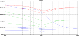
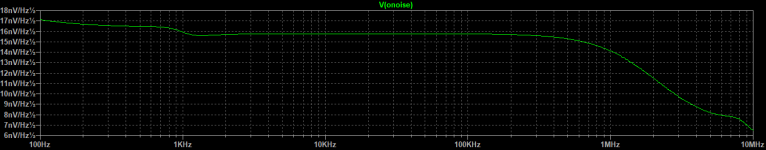
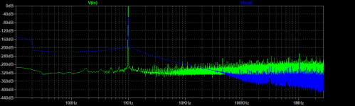
Meanwhile I've made some more simulations concerning the noise performance of the State Variable filter. For the next prototype I could get a quad OPA4134 and some dual OPA1612. Playing around with the passives and optimizing for low impedances (keeping current limits in mind) makes the 1612 a clear favorite here.

At a glance: The uppermost red curve shows the simulated performance of the TL084-prototype that I have built and measured above. It is the configuration with unity first-stage gain and the output buffer set to ~20dB. The other red curves show what could be gained by lowering some resistors and increasing the capacitors.
The green traces show the performance of the OPA4134. It has about half the input voltage noise of the TL, which also halves the overall output noise of the circuit.
The blue traces show the OPA1612 on duty. The upper curve doesn't look that great, which is probably due to the input current noise being almost an order of magnitude higher than that of the FET opamps, in conjunction with the rather high-ish 16k resistors. Reducing those increases the performance considerably, and that is what I will be building next.
Unfortunately I could only get SMD parts, so I'm thinking about having a small board made, instead of botching those things onto veroboard.
Interesting circuit, HpW. I wonder how sensitive it is to parts tolerances and how much matching and trimming will be needed. I know that the Twin-T alone is pretty sensitive already. Maybe I'll run a monte carlo sim when I find some time.
Meanwhile I've made some more simulations concerning the noise performance of the State Variable filter. For the next prototype I could get a quad OPA4134 and some dual OPA1612. Playing around with the passives and optimizing for low impedances (keeping current limits in mind) makes the 1612 a clear favorite here.
At a glance: The uppermost red curve shows the simulated performance of the TL084-prototype that I have built and measured above. It is the configuration with unity first-stage gain and the output buffer set to ~20dB. The other red curves show what could be gained by lowering some resistors and increasing the capacitors.
The green traces show the performance of the OPA4134. It has about half the input voltage noise of the TL, which also halves the overall output noise of the circuit.
The blue traces show the OPA1612 on duty. The upper curve doesn't look that great, which is probably due to the input current noise being almost an order of magnitude higher than that of the FET opamps, in conjunction with the rather high-ish 16k resistors. Reducing those increases the performance considerably, and that is what I will be building next.
Unfortunately I could only get SMD parts, so I'm thinking about having a small board made, instead of botching those things onto veroboard.
Attachments
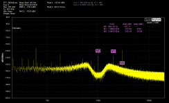
There were questions about the noise characteristics of the AD725D notch filters.
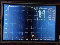
Attached is a scaled plot of the 725D measuring the victor oscillator in rtHz. Marker 3 I could not get to connect to HD3 of the oscillator.
I'm looking though my options for a way to plot the frequency response. The QA does not have a suitable way (not enough resolution).
Attached is a scaled plot of the 725D measuring the victor oscillator in rtHz. Marker 3 I could not get to connect to HD3 of the oscillator.
I'm looking though my options for a way to plot the frequency response. The QA does not have a suitable way (not enough resolution).
Attachments
I'm looking though my options for a way to plot the frequency response. The QA does not have a suitable way (not enough resolution).
I've been eyeing for a PicoScope 4262 lately. It has a full 16bit resolution and manages 10MS/s, with a software that can do 1M FFT in realtime. Noise is specified with 8.5 µV RMS and it has an AWG on board. Of course it is somewhat limited for THD measurements, but with a capable notch in front of it it may well be enough. I'd love to try this thing, but I could not yet justify to part with EUR 1200,-
. Maybe you have the possibility to rent one for a short time and give it a try?QA just published an app note that is quite relevant: Notch Filters
– QuantAsylum which I will need to explore. I have a Picoscope 3206 which I may try and a Bode 100 if I get motivated to set it up.
I used to use a Picoscope on the output of an AP. It worked quite well. The picoscope software is really good. With a good notch you should not need more than 8 bits.
– QuantAsylum which I will need to explore. I have a Picoscope 3206 which I may try and a Bode 100 if I get motivated to set it up.
I used to use a Picoscope on the output of an AP. It worked quite well. The picoscope software is really good. With a good notch you should not need more than 8 bits.
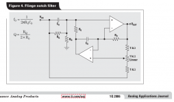
I'm testing Fliege notch right now.
Pro:
1. single pot adjustment central frequency about +-10%;
2. Q easy to set, so harmonics magnitude is correct.
Contra:
1. tendency to oscillate with high GBW OPA;
2. adjustment changes max attenuation level.
Pro:
1. single pot adjustment central frequency about +-10%;
2. Q easy to set, so harmonics magnitude is correct.
Contra:
1. tendency to oscillate with high GBW OPA;
2. adjustment changes max attenuation level.
Attachments
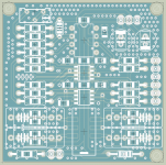
Created a little layout for the SV with two dual SMD OPA1612 and a single DIP LT1028 for additional gain after the notch. One of the OPA's is configured as an input buffer this time, as the input impedance of 1k might be a little low already and too much of a load for Victor's oscillator or any other DUT.
Crammed everything onto 5x5cm, including a relay to switch between two sets of capacitors for 1kHz and 10kHz use. Footprints are there for SMD or THT passives, which may come in handy during experimenting with the best performing values. The small size qualifies for el-cheapo chinese manufacturing, but I think this time I'll opt for some European board house, so I don't have to wait another month or so.
Crammed everything onto 5x5cm, including a relay to switch between two sets of capacitors for 1kHz and 10kHz use. Footprints are there for SMD or THT passives, which may come in handy during experimenting with the best performing values. The small size qualifies for el-cheapo chinese manufacturing, but I think this time I'll opt for some European board house, so I don't have to wait another month or so.
Attachments
QA just published an app note that is quite relevant: Notch Filters
– QuantAsylum which I will need to explore. I have a Picoscope 3206 which I may try and a Bode 100 if I get motivated to set it up.
I used to use a Picoscope on the output of an AP. It worked quite well. The picoscope software is really good. With a good notch you should not need more than 8 bits.
Seems to be a combination of Jim Williams oscillator and a T-notch on a common board. I doubt they get the right performance out of SMD junk parts.
There were questions about the noise characteristics of the AD725D notch filters.
Attached is a scaled plot of the 725D measuring the victor oscillator in rtHz. Marker 3 I could not get to connect to HD3 of the oscillator.
I'm looking though my options for a way to plot the frequency response. The QA does not have a suitable way (not enough resolution).
Here an 3x of your given asc file. The question rises how the 725D compensates the H2 attenuation as about 6.3dB
See below freq. response, 2Khz details, noise analysis..
Hp
Attachments
I'm not sure how accurate my .asc file is. Some aspects are confusing like how to represent the cap neutralization etc. not to mention the potential for errors on my part.
The unit does not seem to have attenuation on H2 so I well might have an error.
I hope to have an extender board soon so I can measure the first notch filter independently. We don't have a schematic of the 725D. The one I worked from was the 725B. The different generations all have small adjustments to some values. My modded first gen 725 gives essentially the same results at the 725D. The critical change seems to be the opamp driving the feedback node.
I'm not sure how accurate my .asc file is. Some aspects are confusing like how to represent the cap neutralization etc. not to mention the potential for errors on my part.
The unit does not seem to have attenuation on H2 so I well might have an error.
I hope to have an extender board soon so I can measure the first notch filter independently. We don't have a schematic of the 725D. The one I worked from was the 725B. The different generations all have small adjustments to some values. My modded first gen 725 gives essentially the same results at the 725D. The critical change seems to be the opamp driving the feedback node.
Well, the freq. figures looks ok! Also the R7/R8 feedback looks ok!
This means, for this values, the Q is not that great. May some compensation happens elsewhere..
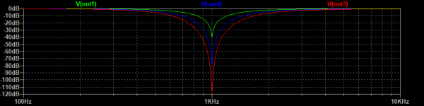
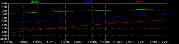
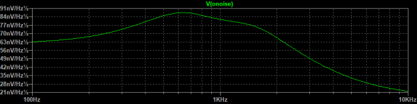
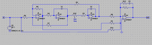
Some latest simulations using an active SVF-Sum Notch using the OPA827...
Real HW to come and verify...
Mira pictures:
. Circuit (may a 20dB gain would look nice too)
. Noise
. THD
. H2 attenuation less than 1 dB
Hp
Real HW to come and verify...
Mira pictures:
. Circuit (may a 20dB gain would look nice too)
. Noise
. THD
. H2 attenuation less than 1 dB
Hp
Attachments
Maths to calculate THD after using a Notch filter
Hi Folks,
could someone help out with the maths necessary to calculate THD after using a passive notch filter.
The set up is as follows:
Viktors oscillator driving the DUT.
The output of the DUT is padded down using a passive R-2R attenuator followed by a low distortion buffer.
This then feeds a Bridged-T Notch filter that goes into a x40 (32dB) amplifier, with a 'balanced' output and into ARTA via a sound card. This is the set up used and recommended by Viktor himself.
I have not built the circuit yet as I want to make sure I understand the maths before I do so.
So, what is the calculation to take into account the reading of the fundamental and harmonics in ARTA, and the attenuation of the second and third harmonics that I can plug into Excel so as to get a valid THD reading?
Thanks and regards
Mike
You mentioned using a bridged-T notch filter. That can work, but did you mean to say twin-T filter, which is what most people have used?
One useful technique to avoid cockpit errors and have a sanity check is to inject a calibration tone at a very low, known level, into the main source oscillator. The second oscillator's frequency can be set wherever you want, except near one of the harmonics. For example maybe midway between the 2nd and 3rd harmonics. If your main oscillator has a non-zero output impedance, like 50 ohms or 600 ohms, you can inject the pilot tone from the second oscillator directly with a high-value resistor, like 1 megohm. With a conventional THD measurement, not using a notch filter, you can adjust the level of the pilot tone to show a known, and easily read, value of "distortion" into the source. This might be 0.01%. You then always keep the setup and your interpretation of the measurement results honest. When the second oscillator is turned on, you will always see its line in the FFT as a known value of distortion.
Cheers,
Bob
- Status
- This old topic is closed. If you want to reopen this topic, contact a moderator using the "Report Post" button.
- Home
- Design & Build
- Equipment & Tools
- Measuring LDO with passive/active notches/filter