Any example where an audio application would exclusively benefit from the XMOS multicore and high speed connectivity architecture?
Amazon Alexa
")
Well, after futzing with CPLDs, FPGAs, STM32s (all work, with good results, the STM32 was actually the most difficult to tame, since the HAL for SAI is buggy as hell) I got to an almost trivial solution for the ADS127L01, that does not require any kind of extra silicon or software, short of the ubiquitous XMOS (except for an extra flip flop if purists want to implement I2S rather than Left Justified (although I see no reason why, for instrumentation purposes).
According to the data sheet, the ADS127L01 Frame Sync mode allows shifting out 32 bit of data (24bit data + 8bit parity) in a full FSYNC period. This is similar to the Left Justifies format, except I2S/Left Justified should send out 64 bit (2x32bit for L and R) in each LRCK period, so the FSYNC signal needs to be twice the LRCK frequency to comply... which is obviously a non trivial thing to do (needs a PLL to double the frequency, and the resulting jitter would still be questionable). The simple solution follows the observation that the FSYNC clock provided by the master (ADS127L01 is in Frame Sync Slave mode) does NOT have to be anywhere close to 50%... the H/L transition is irrelevant, the only things that matter is syncing the L/H FSYNC with the Master clock and BCLK.
This being said, the obvious solution is to halve the FSYNC frequency, so that all 32 bit fit in FSYNC/2; at the same time, the same BCLK is shifting in the ADS127L01 (call it Left ADC) the Right ADC data, so that after a full FSYNC period all 64bits are shifted out from the Left ADC output. The only condition is FSYNc to now be 50% +/- 1 BCLK period, which is ueber easy to provide, anyways.
Of course, the Master, BCLK, LRCK (FSYNC) clocks are generated by the Master XMOS, which configures on the fly the programmable PLL.
I'll post later some data, but the bottom line is ARTA reporting -128dB THD @1KHz and -123dB THD @20KHz, -115dB SNR, all at 192KHz sampling rate, with x128 oversampling in HR mode.
The only significant change is that the two ADCs need and extra GPIO pin from the XMOS chip. This is because any change in the ADC parameters (sampling rate, etc...) requires re-asserting the START pins. A minor change in the XMOS framework code.
Next step is to build a final board, including all the usual trimmings (digital isolators, re-clocking, etc...) and evaluate the performance. It will take some time until I'll be back again.
Last edited:
Thanks, the frame sync slave mode does indeed look like variation of I2S, it is very convenient that the two ADCs can be read with a regular master I2S port. A nice flexible design. IIUC the datasheet a minor inconvenience is the registers are writable only in the SPI mode. But the defaults look sensible and key params are set by pins.
Thanks, the frame sync slave mode does indeed look like variation of I2S, it is very convenient that the two ADCs can be read with a regular master I2S port. A nice flexible design. IIUC the datasheet a minor inconvenience is the registers are writable only in the SPI mode. But the defaults look sensible and key params are set by pins.
It's actually Left Justified, not I2S. As I said, for instrumentation purposes doesn't matter (the XMOS framework code needs a couple of constants change, though, to read Left Justified (instead of I2S) from the ADC Slave), otherwise it would cost an extra flip flop to convert to I2S for strict audio purposes. In such a case, the optional parity bits could no longer be used, since only 31 bits would be included in each half of an I2S frame. But parity bits are not used/useful for audio, anyway.
The datasheet doesn't specify the flexibility of the frame mode, it doesn't mention a frame as being defined by two rising edges of FSYNC, but all timing information is with a 50% FSYNC signal, mentioning bit 15 aligned with the high/low transition of FSYNC, etc... making one believe the FSYNC format is rigid - which is, experimentally, not the case.
I have no problem with any data format, it is simple to change in software.
The minimum t_sclk is specified at 40ns = 25MHz. Daisy-chaining two chips at 512kHz requires 512*64 = 32.768MHz. The 25MHz limit just fits for 384kHz. I asked at TI if that limit is strict...
25MHz, that's the limit for SCLK. Unfortunately, the Master Clock limit is 57nS or about 16MHz. In Frame Sync Slave mode, I could not make it work with a 25MHz Master Clock, or with SCLK frequency larger than the Master Clock Frequency. Which means the Frame Sync Mode is limited to 192KHz.
Only SPI mode allows 16MHz Master Clock and 25MHz SCLK, since the DOUT data should be clocked out only after the DSYNC (data is ready) signal is active.
Thanks, I did not know about the SCLK <= MCLK limit.
What advantages would those single-channel DACs have at 192kHz?
Avoid the noise floor rising at frequecies > 50KHz, that's where this whole ADC exploration started. All audio grade ADCs currently in production have this issue, which precludes measuring any low level harmonics over ~70KHz, anyway falsifying (grossly overestimating) the HF distortion measurements. For those looking forward to measure distortions at low frequencies (<5...10KHz), 48KHz sampling rate is good enough.
This noise floor increase is the effect of the noise shaping implemented in the audio grade ADCs, for the sake of improving the SNR numbers at audio frequencies. A trick to claim outlandish SNR performance at low frequencies, by shifting all the noise power at HF. Industrial grade ADCs (either SAR or delta sigma) don't use such dirty tricks.
P.S. Look at #167, this is one of the best ADCs available today (AK5572), the noise floor approaches -124dB @96KHz, vs. -145dB @ low frequencies. The ADS127L01 has (experimentally) -138dB at all frequencies from zero to 96KHz. Which one would you take for instrumentation purposes?
Last edited:
Now, if anybody out there could pick up and implement an open source robust UAC2 stack on the STM32 platform (there are several chips with the USB 3.0 PHY included) that would be the end of this crap XMOS and the Thesycon closed business model.
I am hearing Thesycon will deliver soon an UAC2 stack on STM32 following the same business model as for the XMOS chipset, that is, "anything that's mostly useless or outdated is free", ****'em.
I am hearing Thesycon will deliver soon an UAC2 stack on STM32 following the same business model as for the XMOS chipset, that is, "anything that's mostly useless or outdated is free", ****'em.
P.S. Look at #167, this is one of the best ADCs available today (AK5572), the noise floor approaches -124dB @96KHz, vs. -145dB @ low frequencies. The ADS127L01 has (experimentally) -138dB at all frequencies from zero to 96KHz. Which one would you take for instrumentation purposes?
Thanks for the explanation. That certainly makes sense.
I considered AK5572 but was fast discouraged by params of its higher-samplerate filters. It looks to me like they took an old (192kHz) design and tapped the filter section to accept higher samplerate, but the actual conversion stage runs basically unchanged.
I will see what TI comes up with, I am afraid no go https://e2e.ti.com/support/data-converters/f/73/t/907168
I can still blaze the dual SPI way...
Attachments
If you want something with a low noise up to 96 kHz you should take a look at the AK5397.
I used it initially, but changed to the AK5394A because the distortion of the AK5394A is lower. But in terms of noise, the AK5397 is better.
I did, and the AK5397 is IMO not up to the task of distortion performance for instrumentation. -108dB is a non starter.
AK5394 is slightly better (still not good enough, IMO), but it's no longer in production, anyway.
syn08:
https://e2e.ti.com/support/data-converters/f/73/p/907168/3354268#3354268
Apparently there should be a way, though a bit more complicated.
If you can disable the STATUS byte with an SPI register write before entering frame-sync slave mode, then there is no issue with using a 24.576-MHz SCLK to daisy-chain two ADS127L01 devices. This would allow you read exactly 48 bits per frame at 512 kSPS. The note in the data sheet assumes that most customers will exclusively use frame-sync mode and will not have the ability to read/write registers prior to data collection.
https://e2e.ti.com/support/data-converters/f/73/p/907168/3354268#3354268
Apparently there should be a way, though a bit more complicated.
syn08:
https://e2e.ti.com/support/data-converters/f/73/p/907168/3354268#3354268
Apparently there should be a way, though a bit more complicated.
Never thought of setting for strict 48bit per frame in SPI mode, then switching to frame sync mode. I have to look closer to this scenario, my gut is telling me it's not a breeze to set up and operate since, to my experience, each START re-asserting is resetting the 32bit mode. Since such a re-assert is required for each parameter change in frame sync mode (oversampling rate, high speed/low power, etc...) it may that this configuration would not be a one time per session thing. Ultimately, it's doable, of course. BTW, in this mode you are stuck in Left Justified mode, since there is no room for I2S without dropping the LSB. No a big deal for instrumentation, but not really an option for strict audio ADC where I2S is the standard.
But otherwise, IMO 384KHz sampling is not a big deal, actually for all I can tell, software like ARTA doesn't even support more than 192KHz. Nice to have, but I wouldn't sweat a bit over it. If >192KHz is really required, there are better options like the 20bit SARs in SPI mode, with the addition of a small CPLD to convert to I2S. I have here an LTC2378 clocked at 100MHz (ok, pushing it a little over the data sheet) and a 4nS MAX V CPLD that spits out 784KHz 20bit I2S without a sweat.
Last edited:
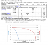
REW supports 1.5MHz (on current linux build, JohnPM has reported a windows REW build to run fine at 768kHz with the RME soundcard), Visual Analyzer tested to work up to 2.3MHz in linux wine (i.e. would run even better natively in windows), octave's (i.e. open source matlab) playrec (ASIO build) and every linux analyzer can run much higher than 192kHz (either out of the box or after trivial change in code). Many soundcards support 384kHz IN/OUT, some do 768kHz. Unfortunately they use the AK5xxxx ADCs whose gain drops at 190kHz (as the figure I posted shows) - but the existing drivers can feed that data rate, even in windows.
It's only a matter of (IMO short) time before every analyzer with healthy support/development will allow this. Adding higher samplerates is simple IF the software is coded soundly. It took a few hours between my question to John and him releasing the build which performed smoothly up to 1.5MHz (and likely higher, had John included a higher option in his java code, likely just adding a number to a static list).
I will explore the options as I need to sample several harmonics for the digital distortion compensation (ADS127L01 should be able to precisely sample H2, H3 for 75kHz fundamental). The ADCs and supporting chips (the balanced buffer, voltage reference, all the LDOs, clock-generator chip) are quite expensive (esp. in smaller quantities) so if a software (i.e. zero variable cost) can allow using them to their maximum capabilities, I want to explore that. I assume a relatively simple python code developed and debugged in a comfortable IDE will take care of all the control.
The I2S (format notwithstanding) support would be a major breakthrough for me because the PCM peripheral on RPi has 32 frames-long input and output buffers, significantly easing timing constraints for servicing IRQs (I2S flow is continuous, unlike the DRDY-timed SPI). The RPi I2S driver is well tested and requires just changing the hard-coded max_rate number from 384000 to 512000.
These are my objectives, everybody has them different which is perfect.
Last edited:
REW supports 1.5MHz (on current linux build, JohnPM has reported a windows REW build to run fine at 768kHz with the RME soundcard), Visual Analyzer tested to work up to 2.3MHz in linux wine (i.e. would run even better natively in windows), octave's (i.e. open source matlab) playrec (ASIO build) and every linux analyzer can run much higher than 192kHz (either out of the box or after trivial change in code). Many soundcards support 384kHz IN/OUT, some do 768kHz. Unfortunately they use the AK5xxxx ADCs whose gain drops at 190kHz (as the figure I posted shows) - but the existing drivers can feed that data rate, even in windows.
It's only a matter of (IMO short) time before every analyzer with healthy support/development will allow this. Adding higher samplerates is simple IF the software is coded soundly. It took a few hours between my question to John and him releasing the build which performed smoothly up to 1.5MHz (and likely higher, had John included a higher option in his java code, likely just adding a number to a static list).
I will explore the options as I need to sample several harmonics for the digital distortion compensation (ADS127L01 should be able to precisely sample H2, H3 for 75kHz fundamental). The ADCs and supporting chips (the balanced buffer, voltage reference, all the LDOs, clock-generator chip) are quite expensive (esp. in smaller quantities) so if a software (i.e. zero variable cost) can allow using them to their maximum capabilities, I want to explore that. I assume a relatively simple python code developed and debugged in a comfortable IDE will take care of all the control.
The I2S (format notwithstanding) support would be a major breakthrough for me because the PCM peripheral on RPi has 32 frames-long input and output buffers, significantly easing timing constraints for servicing IRQs (I2S flow is continuous, unlike the DRDY-timed SPI). The RPi I2S driver is well tested and requires just changing the hard-coded max_rate number from 384000 to 512000.
These are my objectives, everybody has them different which is perfect.
I'm sorry Pavel, you lost me shortly after the beginning... What java code did John (I presume the TI guy?) release, what is 1.5MHz (I presume it's not the ADS127L01 sample rate), which sound cards are doing 768KHz I/O, what is this "ADC gain drops at 190kHz", I thought the 24bit AK ADCs sampling rate is 200k max.
Otherwise, I forgot you are an RPi afficionado, I must admit I'd rather include in a design a CPLD/FPGA/STM32 chip then a generic RPi board. The only scenario I would use an RPi would be a stand alone instrument, with it's own display and entry devices, when the whole UAC2 **** is no longer required. But that's just me...
I believe he is referring to John at REW REW - Room EQ Wizard Room Acoustics Software not TI.
AKM has ADC's including the AK5397 that will sample at 768 KHz however their frequency response rolls off below 200 KHz. The QA401 uses the AK5397 and while its not as low distortion residual as the AK5394 its pretty good still and very cost effective.
Pavel is talking about is software distortion correction process that can correct the distortion of a DAC-ADC chain to a remarkable degree.
I still have not fully conquered REW. I'm still working through Virtins, which is also very capable and also supports NI DAQ cards with higher sample rates. Too many software options to choose among.
Otherwise, I forgot you are an RPi afficionado, I must admit I'd rather include in a design a CPLD/FPGA/STM32 chip then a generic RPi board.
I perfectly understand your position, a hard-coded MCU or FPGA is technically the best way for mere bridging to UAC2. My requirements are different - before the UAC2 transmission I need a rather complicated multithreaded double-precision DSP plus some means of controlling the process from the connected PC. Since I use linux for the processing, RPi4 is basically the only available option. The four 1.6GHz cores will likely be used to max, I would employ more if such a hardware with complete, continously updated, and long-term software support was available. The USB gadget code allows multidevice configuration - the plan is an UAC2 sound device and a USB network card which via autodiscovery and a web server running on the RPi would offer detailed control in web browser on the work PC. USB-audio features cannot provide the needed control plus I would have to create and maintain specific drivers for all major OSes (= nonsense).
The only scenario I would use an RPi would be a stand alone instrument, with it's own display and entry devices, when the whole UAC2 **** is no longer required.
I think people prefer running the actual analysis on their existing PCs with working environments already customized to their individual needs. Moving the analysis to the device would go against this logical trend. Plus RPi4 does not have enough power to run the whole chain including high-resolution display reliably (i.e. with sufficient timing margins).
I think people prefer running the actual analysis on their existing PCs with working environments already customized to their individual needs. Moving the analysis to the device would go against this logical trend. Plus RPi4 does not have enough power to run the whole chain including high-resolution display reliably (i.e. with sufficient timing margins).
That's an interesting conclusion which may, or may not be always true. Personal example: logic analyzer, I got one of those Kingst Chinese USB devices, running at 500MHz timing/100MHz state; comes with a decent PC software and works perfectly for this project. Then I realized I don't have room on my bench for a laptop, powered USB hub, etc... the laptop screen was too tiny to read all the details at high resolution (or I had to spend time and a mouse to scroll through the screen) so I ended up spending a lot of time and effort cruising between the bench and the computer screen 10ft. away. So then I realized an Agilent logic analyzer not only would provide 4GHz timing 600MHz state (not really required here, but nice to have, anyway), 68 channels (instead of 16 with the Kingst device) but it would also not take more space than the USB setup, plus less cable salad on the bench. So I got a second hand 16903A logic analyzer (which is just an old PC running Windows XP, plus the Agilent software) with a 16950A card, for less than the Kingst USB toy. Figure out...
The same (for me) with an audio analyzer, I find much more convenient to use an all-in-one Rohde UPD in the rack than a sound card and cruising to the computer screen to watch the results (plus the advantage of a calibrated instrument). One may argue I need a larger bench, which is indeed true
.
Last edited:
- Home
- Design & Build
- Equipment & Tools
- ADCs and DACs for audio instrumentation applications