This THD compensation feature suggests actually a quite nice implementation detail for instrumentation.
I imagine a "calibration sweep", both in level and frequency, and storing the best THD results in an EEPROM or Flash. Then using (by interpolation) these values for any frequency/level in the instrument range. A trivial task (sweeping, interpolating, setting the THD registers) for any MCU. Though, the sweep (frequency/level/THD registers with searching for an absolute minimum) will take some significant time, but it's a one time "calibration" job.
I imagine a "calibration sweep", both in level and frequency, and storing the best THD results in an EEPROM or Flash. Then using (by interpolation) these values for any frequency/level in the instrument range. A trivial task (sweeping, interpolating, setting the THD registers) for any MCU. Though, the sweep (frequency/level/THD registers with searching for an absolute minimum) will take some significant time, but it's a one time "calibration" job.
Possible, I am suspecting the IV stage has also a large impact on the distortion cancellation, so an apple to apple comparison would be needed to decide.
I am using 2 x OPA1622 + OPA1611 for summation, can't imagine a better combination, low noise, low distortions, high current output for the OPA1622 with the low distortion of the OPA1611. IV resistors are 49.9ohm. The only shortcoming of this config is it denies the op amp rollers the opportunity to exercise their hobby, due to the weird, non standard, OPA1622 chip outline.
Yeah, you probably can't do any better without going to a composite op-amp and the challenges that entails.
This THD compensation feature suggests actually a quite nice implementation detail for instrumentation.
I imagine a "calibration sweep", both in level and frequency, and storing the best THD results in an EEPROM or Flash. Then using (by interpolation) these values for any frequency/level in the instrument range. A trivial task (sweeping, interpolating, setting the THD registers) for any MCU. Though, the sweep (frequency/level/THD registers with searching for an absolute minimum) will take some significant time, but it's a one time "calibration" job.
I wonder how much chip to chip variation there is.
I wonder how much chip to chip variation there is.
I'll find out next weekend, waiting for the revised boards and this time I will populate both channels.
Yeah, you probably can't do any better without going to a composite op-amp and the challenges that entails.
Has anyone here tried that?
I made some test boards recently using the TPA6120A2 in combination with various op-amps, including OPA1612 and OPA1656.
I used two different configurations, one for a line driver and one for a headset amplifier. The results were very promising.
Possible, I am suspecting the IV stage has also a large impact on the distortion cancellation, so an apple to apple comparison would be needed to decide.
I am using 2 x OPA1622 + OPA1611 for summation, can't imagine a better combination, low noise, low distortions, high current output for the OPA1622 with the low distortion of the OPA1611. IV resistors are 49.9ohm. The only shortcoming of this config is it denies the op amp rollers the opportunity to exercise their hobby, due to the weird, non standard, OPA1622 chip outline.
I used OPA1656 everywhere, and 200R IV.
This THD compensation feature suggests actually a quite nice implementation detail for instrumentation.
There is at least one big problem with THD compensation - because ESS's THD value and harmonics level are at the edge of most measurement equipment, and this equipment (ADC) has it's own distortions, so using ESS's THD compensation we make compensation to the common DAC + ADC distortions.
Last edited:
altor,
Hasn't that big problem been largely solved: Digital Distortion Compensation for Measurement Setup
Hasn't that big problem been largely solved: Digital Distortion Compensation for Measurement Setup
There is at least one big problem with THD compensation - because ESS's THD value and harmonics level are at the edge of most measurement equipment, and this equipment (ADC) has it's own distortions, so using ESS's THD compensation we make compensation to the common DAC + ADC distortions.
Right, and that's the purpose of the digital distortion compensation. The measurement device could directly measure, calculate, and output the required compensation polynomial. Or it could fine tune the ESS registers directly in the measurement loop (e.g. by trivial interval halving), just a matter of I2C interface to the DAC. Working on it...
")
I imagine a "calibration sweep", both in level and frequency, and storing the best THD results in an EEPROM or Flash. Then using (by interpolation) these values for any frequency/level in the instrument range. A trivial task (sweeping, interpolating, setting the THD registers) for any MCU.
The MCU would have to be constantly analyzing the signal (level, frequency) to get the interpolation parameters.
When doing this, you can directly apply a picewise compensation polynomial to the signal without tuning the ESS registers, e.g. https://www.diyaudio.com/forums/equ...nsation-measurement-setup-40.html#post6536105
Though, the sweep (frequency/level/THD registers with searching for an absolute minimum) will take some significant time, but it's a one time "calibration" job.
The piecewise polynomial is simple to calculate/estimate from measured spectrum for several levels, multiple polynomials can be obtained for several frequencies and either each applied to corresponding-frequency measurement signal or all averaged for a spread-spectrum musical signal.
Last edited:
Right, and that's the purpose of the digital distortion compensation. The measurement device could directly measure, calculate, and output the required compensation polynomial. Or it could fine tune the ESS registers directly in the measurement loop (e.g. by trivial interval halving), just a matter of I2C interface to the DAC. Working on it...
Is it another way to separate ADC and DAC's harmonics, except using the notch filter?
Has anyone here tried that?
I made some test boards recently using the TPA6120A2 in combination with various op-amps, including OPA1612 and OPA1656.
I used two different configurations, one for a line driver and one for a headset amplifier. The results were very promising.
Been meaning to try it but haven’t gotten around to it. I tested a composite driver for a SAR ADC that worked well, though.
Now THAT was a very interesting thread Mark. Seriously, there are some superb technical DSP and/or measurement projects going on here at the moment, which are in turn pushing the boundaries of DAC and ADC performance, so as to define the reference at a high enough level, within certain specific boundaries and parameters, to reveal nonlinearities that lie within that scope. limited scope = higher precision with the same resources. it all sounds very natural when you put it like that. It is also a kind of feedback loop, as it pushes the DUT to higher and higher levels, which are in turn corrected towards an ideal.
I had wondered when the convolving techniques that have been enabling loudspeaker FIR correction DSP might start to make appearances in other areas of the playback chain. Seems like the ESS distortion correction is an attempt to correct for physical impurities and layout/construction, or rather, departures from the ideal (internal and external), which requires a sort of in situ calibration. deeply interesting stuff, even if the math is beyond my level.
I had wondered when the convolving techniques that have been enabling loudspeaker FIR correction DSP might start to make appearances in other areas of the playback chain. Seems like the ESS distortion correction is an attempt to correct for physical impurities and layout/construction, or rather, departures from the ideal (internal and external), which requires a sort of in situ calibration. deeply interesting stuff, even if the math is beyond my level.
Last edited:
I suspect that any real close compensation for distortion will be very temperature sensitive and will need to be either correcting due to temperature changes or do an analysis/correction before any measurement. This is typical of PPM measurement stuff and in this case is more PPB so very small things will throw your efforts off. Its a fascinating technical challenge.
Here´s a video showing how an app control D2 and D3 of an 9038, and measured by an AP in real time:
E1DA TWEAK App THD Demo - YouTube
E1DA TWEAK App THD Demo - YouTube
Thanks, it's a bit confusing, the author is showing only the 2nd and the 3rd, and doesn't seem to be able to drop the 3rd much under -120dB, which is rather surprising, could be he's using another ESS DAC, not the ES9038PRO in mono mode.
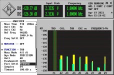
Otherwise, yes, I can drop the 2nd from -115dB at under -135dB (>20dB) as well. For whatever reason, my 3rd starts at -118dB with the registers set to 0, and from there it's not dropping as much as the 2nd, certainly not under -130dB (12dB).
Anyway, at the optimum point, of THD -128dB, 90% are upper harmonics, which are not affected by the correction.
BTW, the involved 16 bit register pairs are in little endian, of course the datasheet is mum about.
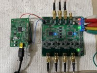
Revised board is up, with both channels running, results are good although I did not bother yet to get the absolute minimum from the 2nd and 3rd harmonic cancellation. To answer a previous question yes, the 2nd and 3rd harmonics are chip dependent, by using two different chips the THD went from -128dB to -118 db, then needed re-adjusting to some +/- 30 LSBs of the registers to bring the distortions back to -128dB or the whereabouts. However, the settings are less chip dependent than I was expecting, clearly the major compensation is targeted toward the I/V circuitry aberrations.
I think I found a bug in the OPA1622 data sheet (or possible I did not read the data sheet close enough). The EN pin is claimed to be logical driven (TTL, according to the level values). This proved to be incorrect; the EN level needs to be TTL high, but on top of the common mode voltage level; better to tie the EN pin to Vcc if one doesn't use the EN functionality.
although I did not bother yet to get the absolute minimum from the 2nd and 3rd harmonic cancellation. To answer a previous question yes, the 2nd and 3rd harmonics are chip dependent, by using two different chips the THD went from -128dB to -118 db, then needed re-adjusting to some +/- 30 LSBs of the registers to bring the distortions back to -128dB or the whereabouts. However, the settings are less chip dependent than I was expecting, clearly the major compensation is targeted toward the I/V circuitry aberrations.I think I found a bug in the OPA1622 data sheet (or possible I did not read the data sheet close enough). The EN pin is claimed to be logical driven (TTL, according to the level values). This proved to be incorrect; the EN level needs to be TTL high, but on top of the common mode voltage level; better to tie the EN pin to Vcc if one doesn't use the EN functionality.
Attachments
- Home
- Design & Build
- Equipment & Tools
- ADCs and DACs for audio instrumentation applications