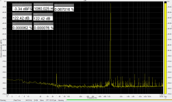
This was my best result from 90389q2m with compensation.
At 7kHz THD is worse, but maybe due to ADC.
This ADC was a little bit noisy, I will try to re-test when Cosmos will come.
At 7kHz THD is worse, but maybe due to ADC.
This ADC was a little bit noisy, I will try to re-test when Cosmos will come.
Attachments

Last edited:
Jens, I was myself not able to bring a ES9038Q2M chip under -110dB THD+N at -1dB (with compensation), that was an heroic effort that included selecting the chip(s) (and destroying a couple of boards in the process). The -110dB i also the number that I see for the best commercial DAC implementations spec, although I don't think they are selecting the chips, so my boards (4 layers) could be 1-2dB less than optimal.
I believe -105dB @-1dB (without compensation) is a fair stating point to tweak the THD compensation, but you need to find out if it is the noise or the THD dominating the THD+N. I suspect it is the THD, so compensating may bring you to about the same numbers as above. I am using OPA1612 in the IV.
Just take a look to the ESS 9038Q2M demoboard and make the same, with compensation you'll see THD+N a bit less than -120db(depends on the chip noise performance), without compensation probably -117db(depends on the chip distortions performance).
Thanks for your feedback.
syn08: I measured THD, not THD+N. Anyway, the noise is relatively low, so I am primarily concerned about the THD for now. The noise can probably be reduced slightly by using a lower noise power supply. I will probably use an op-amp based AVCC to get very low noise.
I have tried with different IV's. The first one with 2xLME49990. The present one with a socket, having tested OPA1612 and OP1656. The results are very similar. I don't have a balanced to single ended op-amp on the output, relying instead on the differential input of the analyzer (RTX6001).
IVX: I am certainly far away from the -117dB without compensation. And that is what's worrying me a bit. My unit is 12dB worse. Could that be due to the circuit/layout or due to variation between chips?
altor: Your results look quite good. Do you have a number for the THD without compensation?
sure, I throw out about 4% of ES9038Q2M to get DR 123db(A) for 9038SG3(ES9038Q2M+AD8397 THD+N -117-115db).I am certainly far away from the -117dB without compensation. And that is what's worrying me a bit. My unit is 12dB worse. Could that be due to the circuit/layout or due to variation between chips?
Attachments
This was my best result from 90389q2m with compensation.
At 7kHz THD is worse, but maybe due to ADC.
This ADC was a little bit noisy, I will try to re-test when Cosmos will come.
do not trust Spectraplus for THD+N ar any noise-related calculations, it is wrong.
This was my best result from 90389q2m with compensation.
At 7kHz THD is worse, but maybe due to ADC.
This ADC was a little bit noisy, I will try to re-test when Cosmos will come.
Interesting, how much is 0dBFS at your DAC output? For me, 0dB is always about 4Veff. It would also be interesting to see your numbers at -0.5dB, -3dB is quite low.
altor: Your results look quite good. Do you have a number for the THD without compensation?
Cannot find a screen shoot. Will measure with Cosmos.
2.8Vrms.Interesting, how much is 0dBFS at your DAC output?
For me, 0dB is always about 4Veff. It would also be interesting to see your numbers at -0.5dB, -3dB is quite low.
Picture above was at -3dB.
No he's using it to heat the ADC. Or rather, I'm assuming, connecting some of the IO ports to ground and then driving them to cause heating in the micro that's glued to the top of the ADC. A thermister is then wired up to an ADC input pin on the micro and used to sense the temperature, with the micro turning the IO ports on and off as required to maintain a specific temperature.
It's probably a very cheap way to do this actually but I'm guessing rather unnecessary.
Can we have curves for performance vs temperature?
It's probably a very cheap way to do this actually but I'm guessing rather unnecessary.
Can we have curves for performance vs temperature?
The curve, especially the realistic one would be quite a difficult task for me. Try to imagine how you can sync the temperature rising with 3rd harmonic dropping down to -145db, or even how to measure the temperature of 5x5mm QFN precisely if any thermocouple+its thermal interface will sink half of the heating power out. Cut the window in the aluminum case against ES9822 and place there a thermal camera? Uhh..
BTW, ESS eng confirmed that poly-resistors in that chip simulating the same way i.e. hotter means better linearity. Of course, if my target was -120db, no reason to care about the thermostat.
BTW, ESS eng confirmed that poly-resistors in that chip simulating the same way i.e. hotter means better linearity. Of course, if my target was -120db, no reason to care about the thermostat.
A thermister is then wired up to an ADC input pin on the micro and used to sense the temperature, with the micro turning the IO ports on and off as required to maintain a specific temperature.
This is what I call a “bang-bang” temperature regulator, and is a rather bad idea (to put it mildly) at under micro volt level. To my experience it generates spurious each time the controller goes “bang”, by induction, radiation, power supply lines, etc… Last time I tried this and learned the lesson the hard way was with a Peltier cooler for a LNA.
Only an analog regulator would be quiet enough to heat the ADC (if that is required for performance, which I doubt is worth the trouble), unless you care only about the SINAD and can ignore the random spikes.
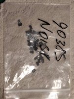
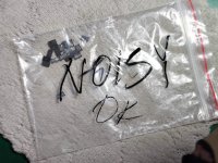
STM8S003 3x3mm(GPIO shorted to GND) + NTC = thermostatic oven.
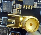
Hmm, would like to exchange the small oscillators or at last one only with a SMA connector, so to glue the SMA on board
 and connect with thin wires to the ADC
  and may terminate with an 50E resistor
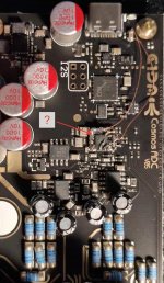
The question rises of the purpose golden & the red cycled area...
So some support required

Hp
Attachments
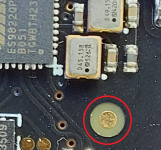
It’s a fudicial that is used as a x,y reference for the component pick n place machine.
99% correct answer but actually fIdUcial, fr.=fiduciaire
So you can tweak a part from -120 to around -145dB just by increasing the temperature?The curve, especially the realistic one would be quite a difficult task for me. Try to imagine how you can sync the temperature rising with 3rd harmonic dropping down to -145db, or even how to measure the temperature of 5x5mm QFN precisely if any thermocouple+its thermal interface will sink half of the heating power out. Cut the window in the aluminum case against ES9822 and place there a thermal camera? Uhh..
BTW, ESS eng confirmed that poly-resistors in that chip simulating the same way i.e. hotter means better linearity. Of course, if my target was -120db, no reason to care about the thermostat.
I am surprised to see such a huge difference with modern IC's.
I had a similar experience with the (old) AK5394A. It has an optimum temperature, where distortion is reduced considerably. One of the advantages of the AK5394A is that it has a built-in heating function
(also known as a rather high power consumption ). The problem was that in general it had to be cooled, which is more difficult than heating a device. I did consider Peltier elements, but ended up using an aluminum bracket to transfer the heat to the chassis.With the ES9822 I guess it might be possible to heat the device with a resistor or two adjacent to the device and a control circuit to keep the temperature at a preset point.
I also tested the newer AK5397 (now also obsolete). With the AK5397 I could not see any THD variation over temperature.
@HpW
Perhaps it would be easier to use a crimp SMA connector with a (very) thin coax cable, like the cables often used inside routers etc.? Of course with AC coupling and termination if needed. The thin cable (perhaps around 1 mm diameter) would remove the risk of mechanical stress.
But THD itself is higher than 5394I also tested the newer AK5397 (now also obsolete). With the AK5397 I could not see any THD variation over temperature.
(especially close to 0dBFS)
- Home
- Design & Build
- Equipment & Tools
- ADCs and DACs for audio instrumentation applications