Off topic, dedicated to Gerhard
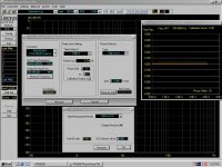
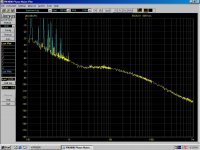
Here's what the PN9000 I got for almost nothing can do; Attached is a 26GHz signal phase noise from a hobby fun level synthesizer I built some time ago. TI LMX2594 chip based plus a Hittite HMC577 doubler, from the time chips were chips in the DigiKey shopping cart, not abstractions in a manufacturer catalogue.
The phase noise sucks, of course, this is only to show what some TLC can do to an instrument.
P.S. Among other minor issues, the 100MHz OCXO was working here and there, more like "there". Since I had nothing better to do with it, I cracked open the Wenzel 2x1 inch metal brick inside, and got the disappointment of my life. A PCB with a discrete PLL driven by an 100MHz, allegedly SC cut, crystal, in a TO5 case. The board had cold solder joints and some corroded PCB traces, from the foam used to isolate the board. Which was certainly acidic, since the insides had a distinct vinegar smell after opening. It's an old VCXO of the 500- series (meaning built to custom specs, no data sheet available for the public) but even so, I was not expecting such blunders from nobody else but Wenzel. Melted the hot glue used to attach the board to the metal shell, pulled the board out, repaired the corroded traces, walked a soldering iron across the solder joints, closed the brick, it is back to life, but to God knows what performances... It will be replaced with a Morion OCXO, anyway, pretty soon.
Attachments
Last edited:
Well I mean -126dB took almost zero effort to achieve. I am absolutely sure you could get quite a bit better than this if you took the time to do so. The power is there, via the THD compensation, you just need to work it long enough to get the desired result.
I don't think getting 0.00002% or whatever is unreasonable. The difficult thing, as you mentioned, is showing that it's stable, repeatable, and consistent across drive level and frequency. It's pointless if it's only useful at one static set of variables.
I don't think getting 0.00002% or whatever is unreasonable. The difficult thing, as you mentioned, is showing that it's stable, repeatable, and consistent across drive level and frequency. It's pointless if it's only useful at one static set of variables.
You could infer assuming the noise is constant across the band. I think it would buy 20 dB in a 100 KHz band if my mental arithmetic is working.
In terms of DR, once you account for BW and A-weighting specs AD4630-24
looks roughly equiv to the stereo ESS Pro ADC.
TCD
The ES9822 THD compensation isn't just limited to the 2nd and 3rd harmonics. You calculate the entire polynomial and coefficients to be programmed into the correction registers.
I am assuming that you could, theoretically, add in as many orders to the equation as you want but the resolution for storing the final result might be limited.
With enough patience, trial and error, and a clean enough signal source, you could compensate down to 0.00002% in my opinion. Whether or not this is necessary, or reliable, is another matter.
I've got a dual mono 9822 acting as slaves. For optimum compensation I'd want to split these into stereo ADCs first and then compensate the left and right channels separately. Then do this for both ADCs. 4 separate sets of finely tuned THD compensation coefficients and out to the 5th harmonic if I really want to push it. I cannot be bothered to do this though.
For simplicities sake I tried using one set of THD compensation coefficients for all 4 channels and only targeted the 3rd harmonic. With the 2nd/4th down at -140dB+ they don't need any attention it's just the 3rd and 5th that really do.
Regardless, the simple compensation gives me 0.00005% THD and 0.00008% THD+N with ARTAs A weighting at 0.5dBfs which is as good as I can realistically expect from the AK4499 signal source as I've measured when using a notch.
The THD compensation holds across frequency and sample rates too.
I've found the platinum sample, kind of king from 26pcs ADCs, with SNR 129.2db(A) and THD+N very close to -125db.
Cosmos ADC DR 129db(A) platinum sample - YouTube
Instead of A-w, you can insert a fake mic response file to limit BW of THD+N in Arta to get +/-.3db matching vs AP digital analyzer. BW20_20k.mic - Google Drive
Last edited:
With enough patience, trial and error, and a clean enough signal source, you could compensate down to 0.00002% in my opinion.
Since the exact algorithm of the linear interpolation is detailed in one of the ESS ANs, IMO there is no need for trial and error. Just measure the distortion vectors, calculate the optimally-compensating polynomial curve of the required order, and enter its values for the interpolation boundaries to the chip.
The THD compensation holds across frequency
Does it indeed in your measurements and to what extent? IME static polynomial compensation fails at lower and higher frequencies https://www.diyaudio.com/forums/equ...trumentation-applications-94.html#post6762435 .
Does it indeed in your measurements and to what extent? IME static polynomial compensation fails at lower and higher frequencies https://www.diyaudio.com/forums/equ...trumentation-applications-94.html#post6762435 .
I didn't save the measurements I took of distortion vs frequency as I only made them quickly. This was to assess whether or not the compensation was working for other frequencies besides the 1kHz I was using to adjust the compensation.
There were no obvious issues at the frequency extremes except for the gentle rise you'd expect to see at high frequencies and then the gentle rise at low frequencies for the AK4499 based on the RC filter created by the vref cap.
5th element, what about SNR you got with 9822?
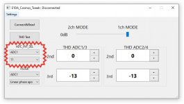
BTW, I brought the ADC_Int_Sel parameters for all 4 ADCs to the Windows app because you can really find a better SNR if you change the recommended 0xB e.i. 11 to something else even different values in the pair ADC1 = 11, ADC3 = 15 as an example. Some chips up to .3-.5db better vs recommended 11.
BTW, I brought the ADC_Int_Sel parameters for all 4 ADCs to the Windows app because you can really find a better SNR if you change the recommended 0xB e.i. 11 to something else even different values in the pair ADC1 = 11, ADC3 = 15 as an example. Some chips up to .3-.5db better vs recommended 11.
Attachments
It depends what program I use. ARTA gives -127.5dB(A) and audioTester -128.7dB(A). These are both with the ADC without any input stage attached though, which obviously causes things to deteriorate.
I actually get better noise figures with an AK5578 in stereo mode, at least with 44/48kHz material. But the ESS DAC gives much better distortion.
I actually get better noise figures with an AK5578 in stereo mode, at least with 44/48kHz material. But the ESS DAC gives much better distortion.
It depends what program I use. ARTA gives -127.5dB(A) and audioTester -128.7dB(A). These are both with the ADC without any input stage attached though, which obviously causes things to deteriorate.
I actually get better noise figures with an AK5578 in stereo mode, at least with 44/48kHz material. But the ESS DAC gives much better distortion.
>> AK5578 in stereo mode
You should get better noise figures with mono mode... interesting that AKM ADC is in noise figures any better.
Or any chance to parallel the ESS ADC to mono mode?
So this means no "Hyperstreaming" used as on DAC.
>> But the ESS DAC gives much better distortion
Is this a tipo, while expected the ESS ADC ...?
I didn't save the measurements I took of distortion vs frequency as I only made them quickly. This was to assess whether or not the compensation was working for other frequencies besides the 1kHz I was using to adjust the compensation.
There were no obvious issues at the frequency extremes except for the gentle rise you'd expect to see at high frequencies and then the gentle rise at low frequencies for the AK4499 based on the RC filter created by the vref cap.
One question just hit me. With the distortion correction does it hold for small changes in frequency? We have a tendency to use nice round numbers like 1KHz. But 997 Hz may well exercise more "bits" in the AD and DA system and highlight any particular steps that are not ideal. We know that Pavel's correction is sensitive to almost everything. Is the ESS more resistant?
ESS distortion performance by frequency has been measured in A Look Inside the New ES9028PRO Converter Chip and the New DAC3 - Benchmark Media Systems - see their chart

My results for static polynomial were very similar to the Benchmark measurements. I calculated two transfer polynomials - from distortions calibrated at 211Hz and 911Hz, they ended up basically identical. It makes sense - static distortions do not change with frequency, being static")
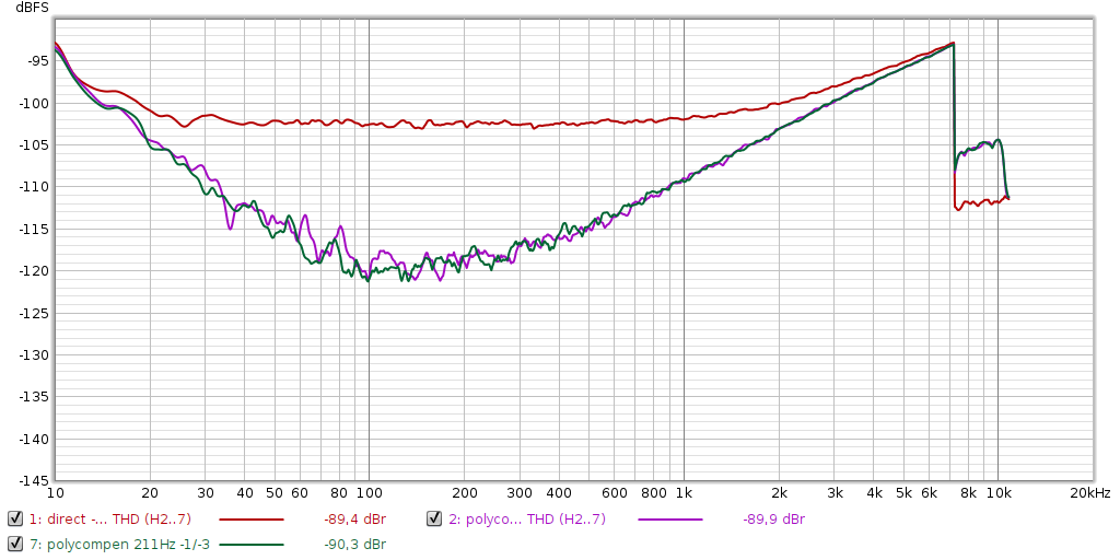
The static distortion compensation tries to straighten the static transfer function (linearity) and as such it applies to any frequency.
As of the performance drop at lower and higher frequencies: For the lower frequencies I assume the THD measurement is affected by the increased 1/sqrt(Hz) noise. For the higher frequencies the dynamic distortions take over the static ones, the distortion phases are rotated from the "static" angles H2: -90deg, H3: -180deg, etc.,
The static compensation adds/subtracts harmonics at the "static" phase angles, as "generated" by the polynomial. The dynamic compensation method I use is employed by many other projects. It's nothing new, I just applied it to the audio measurement chain. It pre-determines amplitudes and phases of the distortions at a specific frequency. The pre-determined distortion tones are re-generated at the same phases and subtracted from the incoming signal when measuring the DUT. Therefore both static and dynamic distortions are handled.
If the distortions are determined (calibrated) at 1kHz, they will apply at 997Hz too, the dynamic distortion profile does not change so wildly. But the compensating H2 has to be generated at 2x997Hz, not at 2x1kHz for which the profile was calibrated. So the dynamic distortion compensation by generating harmonic anti-distortions does not apply only to that exact frequency only, it's valid within a range around the calibration frequency. Width of the range depends on distortion profile of the device, of course. BUT this compensation method requires knowing the fundamental frequency exactly (either by analyzing the incoming signal or getting the info directly from the generator), so that anti-distortion sines are generated at correct frequencies.
The major advantage is maximum performance for a signal containing only single and multiple tones which is the typical signal for measuring ultra-low distortions. Performance of the method depends only on precision of measuring the distortions, theoretically no distortions remain as a harmonic distortion is "only" a sine wave of amplitude and phase, nothing more.
Actually my latest version of the compensating tool compensates the static distortions by a polynomial (for any input signal) and the remaining dynamic distortions if applicable (for pre-calibrated single or multiple tones only).
Recently syn08 linked an interesting paper https://citeseerx.ist.psu.edu/viewdoc/download?doi=10.1.1.39.9650&rep=rep1&type=pdf describing compensation of the dynamic distortions with a dynamic digital filter (they use a low pass filter but any could be used). A digital dynamic filter can change phases at a particular frequency to any degree (unlike the static polynomial filter), therefore it is capable of "generating" the dynamic anti-distortions. Of course every filter is frequency dependent, making the compensation also frequency-dependent. But being "just" a filter it can (to some extent) compensate any signal, like the static (polynomial) filter.
It's an interesting method which IMO could replace the generation of anti-distortion sines. But determining the filter coeffs is not as simple as plain measuring the distortion params by FFT and generating the anti-distortions with opposite phase. It would be a nice topic for masters or even PhD research.
My results for static polynomial were very similar to the Benchmark measurements. I calculated two transfer polynomials - from distortions calibrated at 211Hz and 911Hz, they ended up basically identical. It makes sense - static distortions do not change with frequency, being static
The static distortion compensation tries to straighten the static transfer function (linearity) and as such it applies to any frequency.
As of the performance drop at lower and higher frequencies: For the lower frequencies I assume the THD measurement is affected by the increased 1/sqrt(Hz) noise. For the higher frequencies the dynamic distortions take over the static ones, the distortion phases are rotated from the "static" angles H2: -90deg, H3: -180deg, etc.,
The static compensation adds/subtracts harmonics at the "static" phase angles, as "generated" by the polynomial. The dynamic compensation method I use is employed by many other projects. It's nothing new, I just applied it to the audio measurement chain. It pre-determines amplitudes and phases of the distortions at a specific frequency. The pre-determined distortion tones are re-generated at the same phases and subtracted from the incoming signal when measuring the DUT. Therefore both static and dynamic distortions are handled.
If the distortions are determined (calibrated) at 1kHz, they will apply at 997Hz too, the dynamic distortion profile does not change so wildly. But the compensating H2 has to be generated at 2x997Hz, not at 2x1kHz for which the profile was calibrated. So the dynamic distortion compensation by generating harmonic anti-distortions does not apply only to that exact frequency only, it's valid within a range around the calibration frequency. Width of the range depends on distortion profile of the device, of course. BUT this compensation method requires knowing the fundamental frequency exactly (either by analyzing the incoming signal or getting the info directly from the generator), so that anti-distortion sines are generated at correct frequencies.
The major advantage is maximum performance for a signal containing only single and multiple tones which is the typical signal for measuring ultra-low distortions. Performance of the method depends only on precision of measuring the distortions, theoretically no distortions remain as a harmonic distortion is "only" a sine wave of amplitude and phase, nothing more.
Actually my latest version of the compensating tool compensates the static distortions by a polynomial (for any input signal) and the remaining dynamic distortions if applicable (for pre-calibrated single or multiple tones only).
Recently syn08 linked an interesting paper https://citeseerx.ist.psu.edu/viewdoc/download?doi=10.1.1.39.9650&rep=rep1&type=pdf describing compensation of the dynamic distortions with a dynamic digital filter (they use a low pass filter but any could be used). A digital dynamic filter can change phases at a particular frequency to any degree (unlike the static polynomial filter), therefore it is capable of "generating" the dynamic anti-distortions. Of course every filter is frequency dependent, making the compensation also frequency-dependent. But being "just" a filter it can (to some extent) compensate any signal, like the static (polynomial) filter.
It's an interesting method which IMO could replace the generation of anti-distortion sines. But determining the filter coeffs is not as simple as plain measuring the distortion params by FFT and generating the anti-distortions with opposite phase. It would be a nice topic for masters or even PhD research.
Last edited:
there is some THD+N vs freq as well for ES9822
https://cdn.l7audiolab.com/wp-content/uploads/2021/10/THDN-RatioLoop.jpg
However, 40Hz distortions peak is the setup problem, the test error. Real low-freq THD+N looks like that CosmosADC THDvsFREQ - YouTube
https://cdn.l7audiolab.com/wp-content/uploads/2021/10/THDN-RatioLoop.jpg
However, 40Hz distortions peak is the setup problem, the test error. Real low-freq THD+N looks like that CosmosADC THDvsFREQ - YouTube
You should get better noise figures with mono mode... interesting that AKM ADC is in noise figures any better.
AK5578 is written as providing 127dB(A) in stereo.
ES9822 is written as providing 128db(A) in mono.
AKM specify the 5578 with an input stage attached. With the inputs to the input stage I was using shorted I got 127dB(A) in stereo, thus meeting datasheet specification.
As a test I removed the input stage but kept the input pins biased to their respective common mode voltage with suitable noise filtering. Without an input stage attached the AK5578 measured 130dB(A) in stereo. AKM obviously specify the capabilities of the ADC with an input stage, which makes sense because you can't use it without one
Their evaluation modules providing circuit diagrams and measurements showing how to get the performance they've outlined in the datasheet. It's basically plug and play with you getting what you see.ESS on the other hand? As far as I can tell they are specifying the noise of just the ADC alone. That is without any input stage. I get 128.6dB(A) without the input stage which obviously deteriorates when you connect one. I get about 126.5dB(A) in mono mode with the ES9822 and input stage. Note here that I based my target noise figures for my input stage on the evaluation modules input stage. I thought this would be a safe bet for actually getting 128dB(A) out of the chip in mono but no such luck.
I can only see you being able to get 128dB(A) from it with a golden sample in combination with an unrealistic (for audio) kind of input stage. This is most disingenuous of ESS to characterise the performance of the ADC like this as it promises a level of performance that you just aren't going to get. AKM, on the other hand, deliver what they promise.
Or any chance to parallel the ESS ADC to mono mode?
I assume you mean using two ES9822s per channel? You can only do this with a DSP as far as I can tell.
Is this a tipo, while expected the ESS ADC ...?
Oh dear
You are correct that was supposed to say ADC.One question just hit me. With the distortion correction does it hold for small changes in frequency? We have a tendency to use nice round numbers like 1KHz. But 997 Hz may well exercise more "bits" in the AD and DA system and highlight any particular steps that are not ideal. We know that Pavel's correction is sensitive to almost everything. Is the ESS more resistant?
It definitely did hold with me. In my case the performance of the ADC was only really affected by the 3rd order harmonics. When measured this dominated the entire DAC>ADC signal chain. A 0.5dBfs signal to the ADC basically had all harmonics well below 0.0001% from something like 100Hz-20kHz except for the 3rd. This sat at around 0.00015%.
Whether or not this was from the input stage or the ADC I don't know but I couldn't be bothered trying to figure out. I am using an ADA4945 to drive the ADC directly with 330ohm feedback resistors. I figured it should be capable of much better than 0.00015% at the given drive levels and datasheet so maybe it's the ADC, whatever, it doesn't really matter. With the 3rd order compensated away that neatly brought it in line with the other harmonics giving me a THD of ~0.00005% at 0.5dBfs.
Without the THD comp the 3rd order measured as a flat line from 20Hz-20kHz and sat at the aforementioned 0.00015%. With THD comp on that flat line just shifted down to 0.00003% or something and sat there across the entire frequency bandwidth. With 100kHz bandwidth it went up to around 0.0001% above 20kHz but that was about it.
Clearly the THD comp effectiveness is only as good as the linearity of the rest of the system. My 3rd order was a flat line without any significant deviations at the frequency extremes. This is, apparently, easy to compensate out as it doesn't fluctuate, or require different compensation values for different frequencies. If the ADC driver had shown a significant increase in 3rd order distortion, with rising frequency, then I'm sure the THD comp wouldn't have been anywhere near as effective.
What noise level do these show if you remove the front end?
For measurements, the real noise behavior is on interest, as below 100..200Hz.Not the marketing dBA behavior
This would tell about the required Va/2 reference circuit... can only speak to the ak557x adc.. so the ESS is unknown while no NDA signed...
Hp
- Home
- Design & Build
- Equipment & Tools
- ADCs and DACs for audio instrumentation applications