Hi Guys, new member and first time poster. Just hoping that there may be someone on here who is familiar with repairing these old B&K2209 analogue sound meters??
Background: I already own a calibrated B&K2209 sound meter that works well, but managed to pick up another meter fairly cheaply for parts earlier this year. (It's a fairly late model one in the serial number range above 699000, which i suspect is late 1970's, and this 2209 model was apparently discontinued by 1980 ??). After repairing the corroded battery terminals (seems to be a common problem) i tested the meter for basic function and surprisingly most of it seemed to work ok. The one significant problem though is that the peak hold function is not working properly - doing a basic 'hand clap' test near the meter the needle will deflect (right) up the scale and partially 'hold', but then starts slowly falling back to the left (towards zero). In order for the meter to meet specification, the needle must not fall more than 0.5db over 1 minute duration.
This was 7-8 months ago. I purchased the B&K2209 service manual online, and have had a look through that, and looked for other info online, including another thread about B&K2209 on this site from 2 years ago. I have checked out most of the old electrolytic capacitors. I ordered some replacement electrolytic capacitors as well as some polyester ones also (which showed obvious signs of cracking) where the capacitance readings were a little high. One of the electrolytics in particular was 50% low.
Anyway, things got really busy with my work so this (as a hobby/project) job got put on the back burner for 6 months. Finally got to have a look at it again in the last few days (due to Christmas break) and replaced some of the components i had ordered months ago. I have adjusted one of the potentiometers to get the correct 200V polarisation voltage for the pressure microphone. Then tested the meter for correct function. The problem with the peak hold (not 'holding') still exists.
I had assumed that it was maybe a bad cap not holding it's charge. But could it be something else like a bad diode leaking current back? Or something else, like the 'reset' switch for the peak hold function gone bad??
Just a long shot, but i figured that this issue with the peak hold function may be a common problem with these BK2209 meters, and that there might (hopefully") ) be someone on here who knows exactly where the fault lies ??
) be someone on here who knows exactly where the fault lies ??
FWIW, I did my apprenticeship as an electrical and refrigeration tech in my teens/20's, but have been out of that industry for 25 years now. I am no whizz on electronics, but i can do basic component testing and simple diagnostics. Electronics was never really my thing though. For the past 23 years i have been involved in Gunsmithing, and that is what the sound meters are for (suppressor testing).
Thanks in advance for any assistance.
Regards, Dean.
NZ.
Background: I already own a calibrated B&K2209 sound meter that works well, but managed to pick up another meter fairly cheaply for parts earlier this year. (It's a fairly late model one in the serial number range above 699000, which i suspect is late 1970's, and this 2209 model was apparently discontinued by 1980 ??). After repairing the corroded battery terminals (seems to be a common problem) i tested the meter for basic function and surprisingly most of it seemed to work ok. The one significant problem though is that the peak hold function is not working properly - doing a basic 'hand clap' test near the meter the needle will deflect (right) up the scale and partially 'hold', but then starts slowly falling back to the left (towards zero). In order for the meter to meet specification, the needle must not fall more than 0.5db over 1 minute duration.
This was 7-8 months ago. I purchased the B&K2209 service manual online, and have had a look through that, and looked for other info online, including another thread about B&K2209 on this site from 2 years ago. I have checked out most of the old electrolytic capacitors. I ordered some replacement electrolytic capacitors as well as some polyester ones also (which showed obvious signs of cracking) where the capacitance readings were a little high. One of the electrolytics in particular was 50% low.
Anyway, things got really busy with my work so this (as a hobby/project) job got put on the back burner for 6 months. Finally got to have a look at it again in the last few days (due to Christmas break) and replaced some of the components i had ordered months ago. I have adjusted one of the potentiometers to get the correct 200V polarisation voltage for the pressure microphone. Then tested the meter for correct function. The problem with the peak hold (not 'holding') still exists.
I had assumed that it was maybe a bad cap not holding it's charge. But could it be something else like a bad diode leaking current back? Or something else, like the 'reset' switch for the peak hold function gone bad??
Just a long shot, but i figured that this issue with the peak hold function may be a common problem with these BK2209 meters, and that there might (hopefully
) be someone on here who knows exactly where the fault lies ??FWIW, I did my apprenticeship as an electrical and refrigeration tech in my teens/20's, but have been out of that industry for 25 years now. I am no whizz on electronics, but i can do basic component testing and simple diagnostics. Electronics was never really my thing though. For the past 23 years i have been involved in Gunsmithing, and that is what the sound meters are for (suppressor testing).
Thanks in advance for any assistance.
Regards, Dean.
NZ.
First suspect peak hold capacitor. Done!
Second, diode feeding capacitor.
Third input to the buffer amplifier.
Fourth lubrication on the reset switch has oxidized and is conductive.
Fifth is dirt in the assembly is conductive.
If all are good repeat the process a replacement part may be bad. Particularly the sample hold capacitor may need to be a special part.
Thanks Simon,
I couldn't really identify exactly which capacitor was 'the one' for the peak hold function (if there was only one), but just checked as many caps as i could and noted the ones that seems to be out of nominal capacitance by 30% or more. I realise that there may still be a dud one in there that maybe reads ok with the fluke 12 meter (capacitance test), but in practice it may be a leaker.
I will check out the reset switch and diodes when i get a chance, but in the meantime if anyone is out there who has experience in working on the B&K2209's then please chip in with any advise or suggestions to help me to rectify this fault, as it would be great to get this meter going to be able to use it as a backup or secondary-position sound meter for our suppressor tests.
Thanks, Dean.
Without knowing the circuit details we are just guessing... but it all looks very old school so I'm guessing not even any opamps in there.
The sample and hold function may use a FET type transistor and cap (not necessarily an electrolytic) but we need more details.
Corrosion can cause leakage within PCB material itself and a S/H circuit would be affected by even a microscopic leak.
The sample and hold function may use a FET type transistor and cap (not necessarily an electrolytic) but we need more details.
Corrosion can cause leakage within PCB material itself and a S/H circuit would be affected by even a microscopic leak.
Without knowing the circuit details we are just guessing... but it all looks very old school so I'm guessing not even any opamps in there.
The sample and hold function may use a FET type transistor and cap (not necessarily an electrolytic) but we need more details.
Corrosion can cause leakage within PCB material itself and a S/H circuit would be affected by even a microscopic leak.
Thanks Mooly, there is one FET transistor that appears adjacent to the reset switch ('V604' FET N-channel E102) and there is a Polyester cap ('C604' 0.15uF/100V), and there looks like a diode above that as well.
Are the FET type transistors commonly prone to failure?
The guy that i got the service manual from has refused permission for me to post the circuit diagrams publicly. But if you are able to help me out then i could possibly email or PM a pic of the circuit in question directly to you?
Thanks, Dean.
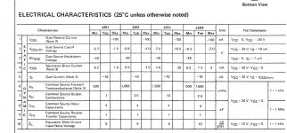
The E102 is a very old Siliconix device and according to the 1986 Siliconix data book is replaced by a J201 (and all these are long since obsolete).
Before condemning the FET you should look for signs of any contamination on the board that could cause leakage. You can sometimes get an idea by simple trying to see if there is voltage on the board material itself, just press the meter probe into the paxolin or fibreglass and see if you can read voltages. If you can then the board itself has become conductive.
It wouldn't take much to upset such a circuit, for example 100 meg ohms leakage across the 0.15uF cap or around the FET would give a time constant of just 15 seconds, the time taken for the sample voltage to fall exponentially to just 37% of its initial value.
I would probably clean that area of the board first and see if it altered things, then look at cleaning the FET package and the cap around the legs and finally swapping the FET, diode and cap.
Try a 2N3819 for the FET (different pin out).
If we are still stuck after that then I'll take a look at the circuit I've sent you a pm...
Edit... and make sure the switch has no leakage either. Maybe disconnect it if it is hard wired. 100 Meg type values of leakage are much to high to measure on a normal DVM's and wouldn't show.
Before condemning the FET you should look for signs of any contamination on the board that could cause leakage. You can sometimes get an idea by simple trying to see if there is voltage on the board material itself, just press the meter probe into the paxolin or fibreglass and see if you can read voltages. If you can then the board itself has become conductive.
It wouldn't take much to upset such a circuit, for example 100 meg ohms leakage across the 0.15uF cap or around the FET would give a time constant of just 15 seconds, the time taken for the sample voltage to fall exponentially to just 37% of its initial value.
I would probably clean that area of the board first and see if it altered things, then look at cleaning the FET package and the cap around the legs and finally swapping the FET, diode and cap.
Try a 2N3819 for the FET (different pin out).
If we are still stuck after that then I'll take a look at the circuit
I've sent you a pm...Edit... and make sure the switch has no leakage either. Maybe disconnect it if it is hard wired. 100 Meg type values of leakage are much to high to measure on a normal DVM's and wouldn't show.
Attachments

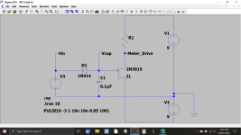
Just posting this in the hope it will clarify how the FET operates. The load on the FET (the meter) should not have any real impact on things.
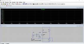
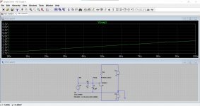
Diagram #1 shows the basic circuit of an FET sample and hold.
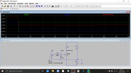
Diagram #2 and 3 shows a 50 millisecond negative going pulse applied to the diode. That is the green trace labelled Vin.
The blue trace is the voltage on the cap. Having initially charged to the peak pulse voltage (less the diode forward volt drop) it is then slowly decreasing over time due to leakage of the diode. The diode simulation model includes this property although I don't know how accurate it is.
(I must admit I'm surprised how much a I1N4148/914 type diode in simulation at least has such an effect... must look at the real data sheets for these)
The red trace is the meter drive voltage. The FET has essentially no gate current and so how the voltage across the cap is maintained depends solely on four things:
1/ Is the cap leaky? No... you have proved this.
2/ Physical leakage due to contamination.
3/ Diode leakage.
4/ A faulty FET.
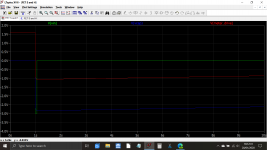
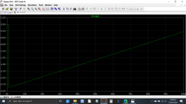
The last image shows the cap voltage over 100 seconds using the simulation models leakage current for the diode as the factor that pulls it down.
Diagram #1 shows the basic circuit of an FET sample and hold.
Diagram #2 and 3 shows a 50 millisecond negative going pulse applied to the diode. That is the green trace labelled Vin.
The blue trace is the voltage on the cap. Having initially charged to the peak pulse voltage (less the diode forward volt drop) it is then slowly decreasing over time due to leakage of the diode. The diode simulation model includes this property although I don't know how accurate it is.
(I must admit I'm surprised how much a I1N4148/914 type diode in simulation at least has such an effect... must look at the real data sheets for these
) The red trace is the meter drive voltage. The FET has essentially no gate current and so how the voltage across the cap is maintained depends solely on four things:
1/ Is the cap leaky? No... you have proved this.
2/ Physical leakage due to contamination.
3/ Diode leakage.
4/ A faulty FET.
The last image shows the cap voltage over 100 seconds using the simulation models leakage current for the diode as the factor that pulls it down.
Attachments
> decreasing over time due to leakage of the diode..... (I must admit I'm surprised how much a I1N4148/914 type diode...
Small-signal (computer) diodes are doped for good conduction in small size (speed, price).
It was common to find a JFET Gate-channel diode used as the passive peak switch. A JFET Gate does not need high conduction, and the only great feature of JFETs is small input current. JFET gates will reliably have lower leakage than any common diode
To meet a "0.5db over 1 minute" spec we need super low leakage in several parts, so probably more to it than your tutorial shows. The old app-books are coming apart, but I remember bootstrapping a diode-connected JFET so it had zero voltage in the hold mode.
(You've seen the audio switch with a diode driving a JFET gate? It looks like it can't work, the arrows are in opposition. In fact it works reliably because of diode leakage being greater than Gate leakage.)
Yes, I have seen the JFET switching you mention, I think NAD relied on leakage in one of their designs.
In the simulation I found that LED's had the best (lowest) leakage. This is with and then without the FET and running for 10,000 seconds.
In the simulation I found that LED's had the best (lowest) leakage. This is with and then without the FET and running for 10,000 seconds.
Attachments
...In the simulation I found that LED's had the best (lowest) leakage....
In the 1970s I was troubled with quite high leakage in LEDs.
That's surely changed. But if you are just going by sim models, ask why a light modeler would even consider leakage.
I've no experience re leakage of LEDs, but I do know they can be photo-receptors as well as emitters. So if you try LEDs for low leakage, make sure they are completely blocked from ambient light to preclude any photocurrent leakage.
Good luck!
In the 1970s I was troubled with quite high leakage in LEDs.
That's surely changed. But if you are just going by sim models, ask why a light modeler would even consider leakage.
Thanks guys
it was just curiosity of leakage in different sim models I was looking at. I wouldn't recommend trying LED's as a substitute for a diode in an already commercially produced unit.Reality check...
I cobbled an LF353 opamp as a voltage follower on a breadboard running it off a 9v PP3 battery. On the + input I connected a 0.1uF 63V MKT film cap to the zero volt line and brought the opamp output voltage to 5 volts by careful dabbing of a finger to the 9 volt supply (note we are in high tech true engineer mode now).
The opamp held the voltage steady and on a 3.5 digit DVM it fell from 5.00 to 4.99 volts after two to three minutes. Pretty good for a breadboard layout.
Now I repeated the test with a 1N4148 in parallel to the cap. Now the voltage fell to 4.75V after just 10 seconds and hit 4.5 after 20.
That's a true reality check that resets my thoughts. I wouldn't have said it would have pulled it down that fast if just asked... but it did.
A red LED was a bit better but not much (I didn't shield it from light but the room was dull with no artificial light on) and it hit 4.5V after half a minute or so.
So there we are
I cobbled an LF353 opamp as a voltage follower on a breadboard running it off a 9v PP3 battery. On the + input I connected a 0.1uF 63V MKT film cap to the zero volt line and brought the opamp output voltage to 5 volts by careful dabbing of a finger to the 9 volt supply (note we are in high tech true engineer mode now
). The opamp held the voltage steady and on a 3.5 digit DVM it fell from 5.00 to 4.99 volts after two to three minutes. Pretty good for a breadboard layout.
Now I repeated the test with a 1N4148 in parallel to the cap. Now the voltage fell to 4.75V after just 10 seconds and hit 4.5 after 20.
That's a true reality check that resets my thoughts. I wouldn't have said it would have pulled it down that fast if just asked... but it did.
A red LED was a bit better but not much (I didn't shield it from light but the room was dull with no artificial light on) and it hit 4.5V after half a minute or so.
So there we are
In the 1970s I was troubled with quite high leakage in LEDs.
That's surely changed.
Yes, LED/semiconductor laser tech has moved on a bit(!) I suspect GaN based devices are very different due to the large bandgap and modern heterojunction structures. LEDs are more complex than BJTs these days.
Bob Pease offered diode leakage advice in some of his columns. If memory serves (uncertain these days), 4148 diodes have gold doping to improve switching speed at the expense of leakage. He recommended using a transistor's base-collector as a low leakage diode. I believe he also mentioned using the gate-channel junction of a jfet. Sorry that I can't point to specific link.
 Link to copyright material removed. If you can provide proof that it is not restricted, the link can be restored.
I suspect the diode is part of the original circuit so it's characteristics would already be accounted for. I have found in old General Radio sound level meters the lubricant used on the switch contacts becomes conductive from oxidation and causes the meters to fail. Using alcohol to clean out the switches and then lubricating it with modern chemicals fixes the meters.
Hi Guys, seeing as there has been a flurry of activity on this thread recently i felt i should give a quick update on progress to date.
I appreciate all the help and information that has been put forward, but must acknowledge the assistance of Mooly in particular who has been really helpful and PM'd me with some good info.
So we have eliminated the following possible faults:
1. The capacitor C604 seems to be good. (Polyester 0.15uF/100V)
2. There is no leakage across the reset switch (with the switch disconnected the needle drop still occurs).
3. Same with the 'diode' Q601 (a Si. trans NPN SF115A) that seems to be working ok.
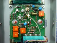
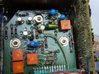
4. The most likely cause remaining is the FET (shown on the parts list as an E102 N-channel), but on this particular unit they seem to have used a Teledyne 2N4302 (7234) 'Glob top' instead. (See pics attached).
So, at this stage i think i have managed to find a source in the UK for the old FET's, so i will order a few of those and hopefully in another week or two when they arrive (and i have time to look at the meter again) i will try a new FET and see how it goes, then report back.
Thanks, Dean.
I appreciate all the help and information that has been put forward, but must acknowledge the assistance of Mooly in particular who has been really helpful and PM'd me with some good info.
So we have eliminated the following possible faults:
1. The capacitor C604 seems to be good. (Polyester 0.15uF/100V)
2. There is no leakage across the reset switch (with the switch disconnected the needle drop still occurs).
3. Same with the 'diode' Q601 (a Si. trans NPN SF115A) that seems to be working ok.
4. The most likely cause remaining is the FET (shown on the parts list as an E102 N-channel), but on this particular unit they seem to have used a Teledyne 2N4302 (7234) 'Glob top' instead. (See pics attached).
So, at this stage i think i have managed to find a source in the UK for the old FET's, so i will order a few of those and hopefully in another week or two when they arrive (and i have time to look at the meter again) i will try a new FET and see how it goes, then report back.
Thanks, Dean.
Attachments
Further update, just out of interest i managed to find (google) a PDF copy online of an older 2209 service manual (from serial # 496282 onward that was posted online by someone in Sweden i think?) so i think there should be no copyright issues with attaching a couple of pages on here. (plus they are from the early 1970's, and obsolete models, so i would think that any claims of ownership/copyright of info that is already in the public domain would be invalid.) As far as i can see the details seem to be the same as for the later models in the 670xxx range,
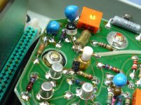
Also, the previous pics i posted of my faulty meter (serial # 699xxx) showed the FET as a teledyne glob top unit. I will attach here a pic from my other meter (functional and calibrated - serial # 670xxx) that shows the 'V604' FET as a metal-top original E102 7528 unit, which is what is listed on the parts/layout sheet. So i'm not sure, but it's possible that at some stage they changed over to using Teledyne 2N4302 FET's instead of the old E102 N-channel FET's ?
There are B&K 2209 service manuals also listed on Ebay.
Attachments
- Status
- This old topic is closed. If you want to reopen this topic, contact a moderator using the "Report Post" button.
- Home
- Design & Build
- Equipment & Tools
- Bruel & Kjaer 2209 sound meter repairs - peak hold problem