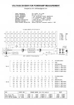
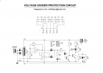
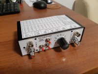
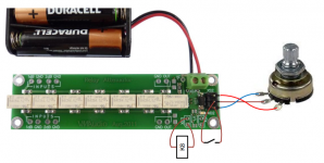
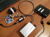
the voltage divider prototype enclosure, inside is still empty, pcbs are on the way
it's my voltage divider with MCU and LiPo battery
step 1dB
Attachments
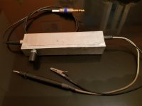
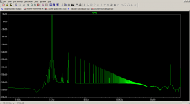
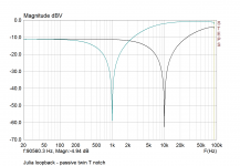
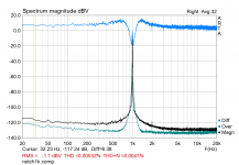
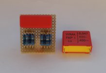
I finished and measured the 10k passive notch filter. Depth is 60dB, pretty good.
Attachments
Last edited:
Looks good! I'm waiting for my PCBs to be delivered.
Jan
yea ... next step is a post-notch 30-40dB amp (same box as for notch, two 9V battery powered)
Attachments
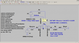
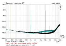
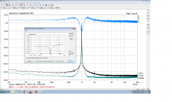
I tried to compensate the notch1k filter in ARTA. The compensation file was generated by STEPS.
green trace - soundcard loopback
black trace - loopback with notch + compensation (*.mic file)
blue trace - green black difference
H1 diff -0.8dB
H2 diff +1.37dB
H3 diff -0.04dB
green trace - soundcard loopback
black trace - loopback with notch + compensation (*.mic file)
blue trace - green black difference
H1 diff -0.8dB
H2 diff +1.37dB
H3 diff -0.04dB
Attachments
Last edited:
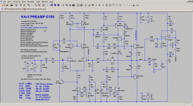
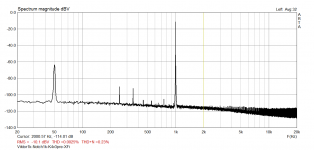
preamp quick test
the chain : Viktor1K -> Notch1k -> PreampK4v3 -> XFi
Viktor1K output: +4.4dBv
Notch attenuation: H1 -55dB, H2 -9dB, H3 -5dB
Preamp : +40dB
X-Fi input: -10dBv
After correction:
H1 = -10+55 = +45dB
H2 = -114+9 = -105dB (at least)
H3 = -117+5 = -112dB (at least)
I hope I am correct ... THD < -145dB
the chain : Viktor1K -> Notch1k -> PreampK4v3 -> XFi
Viktor1K output: +4.4dBv
Notch attenuation: H1 -55dB, H2 -9dB, H3 -5dB
Preamp : +40dB
X-Fi input: -10dBv
After correction:
H1 = -10+55 = +45dB
H2 = -114+9 = -105dB (at least)
H3 = -117+5 = -112dB (at least)
I hope I am correct ... THD < -145dB
Attachments
Last edited:
I find that disposable aluminium baking trays are a simple way to supress mains hum on the workbench - one to hold everything, and one to act as cover.
https://www.amazon.co.uk/10pcs-Disposable-Aluminium-Baking-Trays/dp/B00JF0TWS2
https://www.amazon.co.uk/10pcs-Disposable-Aluminium-Baking-Trays/dp/B00JF0TWS2
I find that disposable aluminium baking trays are a simple way to supress mains hum on the workbench - one to hold everything, and one to act as cover.
https://www.amazon.co.uk/10pcs-Disposable-Aluminium-Baking-Trays/dp/B00JF0TWS2
cool

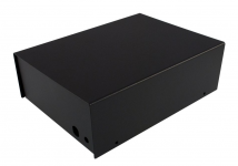
I'll use steel enclosure (162x70x217 mm) for the final preamp. Inside : R-core transformer, super reg (jung) and two K4v3 modules (20dB and 40dB amplification).
Attachments
Yeh, some form of total test setup Faraday cage (with all equipment inside, including batteries and interconnecting cables), with only USB cable exit, can often supress local stray hum ingress.
I do the same with my EMU0404 when testing an amp on the bench - the EMU sits in an aluminium tray, with exit hole for 100:1 probe to go to bench DUT, and exit hole for line output lead, and another for USB. Battery powering for EMU (and if needed also for USB isolator) sits in tray as well. A ground clip link from line input BNC cover to tray also seems to help sometimes, as does inverting a tray over the top to make a total cage.
I do the same with my EMU0404 when testing an amp on the bench - the EMU sits in an aluminium tray, with exit hole for 100:1 probe to go to bench DUT, and exit hole for line output lead, and another for USB. Battery powering for EMU (and if needed also for USB isolator) sits in tray as well. A ground clip link from line input BNC cover to tray also seems to help sometimes, as does inverting a tray over the top to make a total cage.
...if needed also for USB isolator...
Which USB isolator do you use? EMU 0404 is high speed (480Mbps). Thanks.
I have used a ADuM4160 based pcb that was on ebay years ago - it has a 'full speed' data rate setting, so I can get 48kHz sampling rate from the EMU if needed. I typically used the USB isolator for cheap USB soundcards I was checking out, as I was keeping the EMU for reference measurements back then. I haven't had to use it for the EMU now I think about it - and use a battery power interface for the EMU when checking for hum loop parasitics.
- Status
- This old topic is closed. If you want to reopen this topic, contact a moderator using the "Report Post" button.
- Home
- Design & Build
- Equipment & Tools
- Power amp measurement system