EDIT: Sep 15 2019. It is advised to read the whole thread before start doing anything with your soundcard. There are revisions that make previous posts invalid!
Honestly, this Test & Measurement interface for Soundcard together with ARTA was more than enough for my humble tube projects. But it couldn't do impedance measurements with ARTA limp. It has been explained that those cheap soundcards don't have adequate input channel separation for this job. Understood... So, I spent the double and got UMC202. I was pleased to see that as is from the box it does excellent impedance measurements without even requiring the headphone output for reasonable loads! And with an amp -Rod Elliott's workbench amp fitted with ARTA limp probe- it can measure coils with very low DCR. If anything else, it would be a keeper just for this. But I wanted to explore possibilities for FFT as well. The short answer is not as it comes from the factory... Bellow is the best I could get.
 It makes sense. It has high gain input preamps and perhaps tuned for some musical distortion. I decided to tweak it based on some empirical experience from previous similar projects. What I thought it would be a weekend's project, it took more than a month -OK, half an hour per day. So I managed to isolate the audio codec converter http://www.mouser.com/ds/2/76/cs4272_f1-43250.pdf -ADC/DAC- and its input buffer and immediately there was a significant improvement in performance.
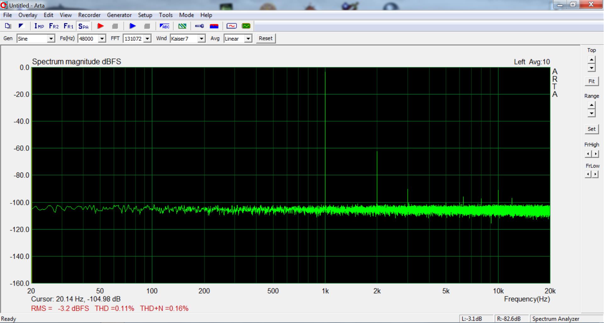
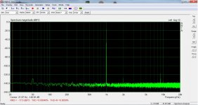
 Still, two problems. It was clear only up to -17,6dB and there was a high frequency peak - here at 9kHz but from day to day I've seen it anywhere between 8 and 11kHz. It took a lot of sniffing around, mostly because of my ignorance. You can read here a small part of it SE to BAL conversion with active filter The conversation and some more reading helped to find my way at least to some point. This paper was very helpful https://d3uzseaevmutz1.cloudfront.net/pubs/appNote/an241-1.pdf. At page #5 there is what I found inside the UMC 202 more or less. There were some differences -red in the schematic bellow
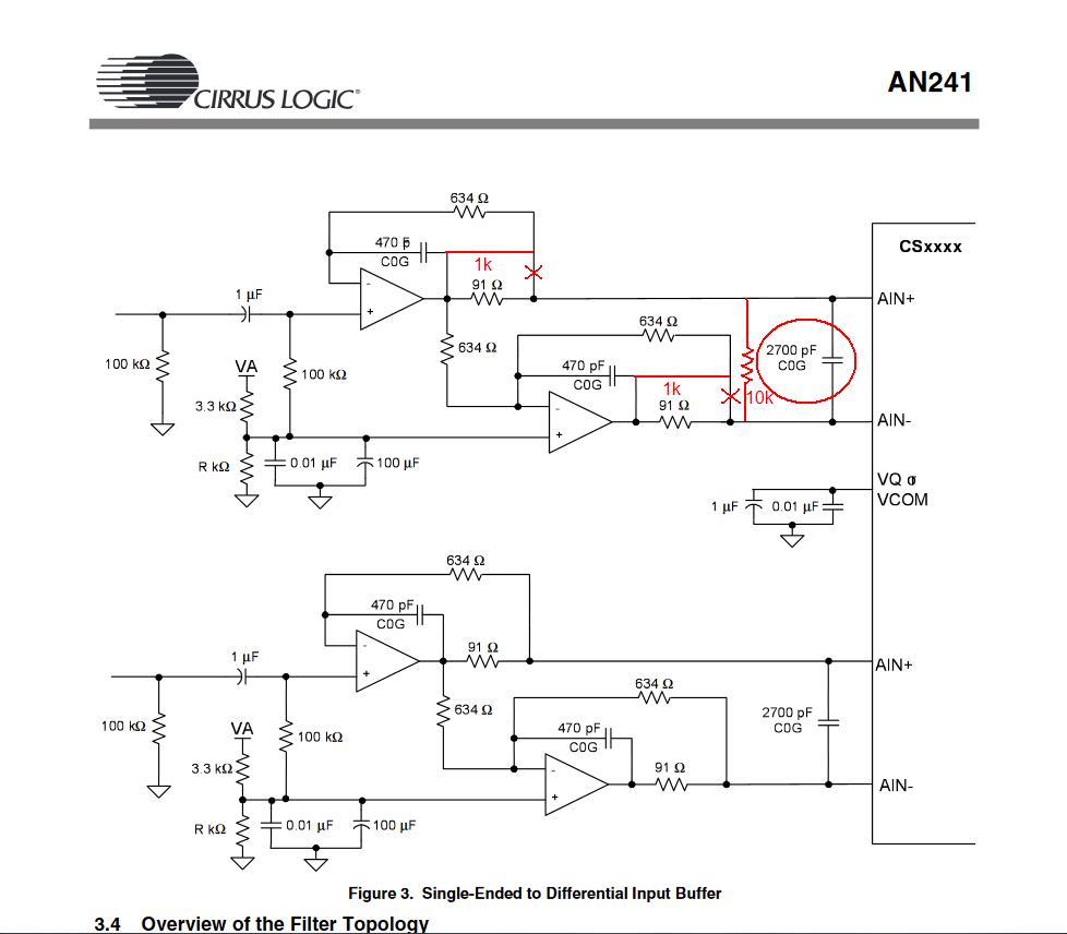 Too high output resistors for the op amps and another one across the differential inputs. I've seen that in some designs marked as "optional". Perhaps an attempt to avoid hard clipping as this soundcard is primarily meant for musicians? I can't tell. But I know that replacing the 1k resistors with 91R and removing completely the 10k resistors was another good step.
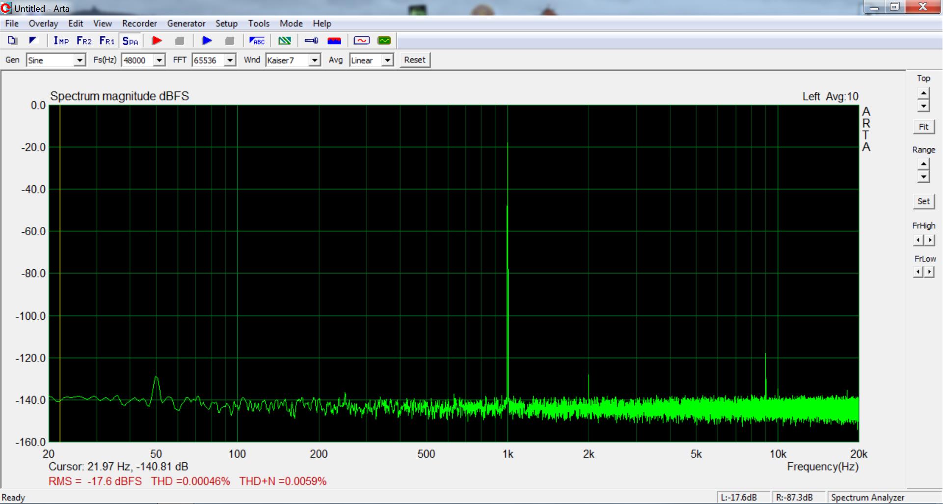
 Unfortunately, the high frequency peak is still there together with its k2 harmonic and +/-1kHz IMD. The graph would be much cleaner without it. I made the thought that the capacitor circled in red in the previous schematic could be responsible for this -very low? I tried to add 1nF polystyrene caps in parallel with them. I think I saw a tiny improvement but I can't tell for sure. Any ideas about this would be very much appreciated. I can provide some more info about that.
So, at the end the feelings are mixed... I could spend a little more, or maybe a little much more and get something ready that does better, but I started from very little money and stayed there, plus DIY satisfaction and knowledge gained. I was even tempted to design a soundcard from scratch but it is the software that repeals me. The driver's functionality is very important and I've seen manufacturers failing in this domain. Apparently, Behringer does this right.
I talk about Behringer, ARTA and Pete Millett's PC interface. I do not have any relationship with these other than I use them as a low cost measurement rig.
In case anybody would be interested on the modifications, I can provide all the details.
Thanks for reading!
Honestly, this Test & Measurement interface for Soundcard together with ARTA was more than enough for my humble tube projects. But it couldn't do impedance measurements with ARTA limp. It has been explained that those cheap soundcards don't have adequate input channel separation for this job. Understood... So, I spent the double
and got UMC202. I was pleased to see that as is from the box it does excellent impedance measurements without even requiring the headphone output for reasonable loads! And with an amp -Rod Elliott's workbench amp fitted with ARTA limp probe- it can measure coils with very low DCR. If anything else, it would be a keeper just for this. But I wanted to explore possibilities for FFT as well. The short answer is not as it comes from the factory... Bellow is the best I could get. So, at the end the feelings are mixed... I could spend a little more, or maybe a little much more
and get something ready that does better, but I started from very little money and stayed there, plus DIY satisfaction and knowledge gained. I was even tempted to design a soundcard from scratch but it is the software that repeals me. The driver's functionality is very important and I've seen manufacturers failing in this domain. Apparently, Behringer does this right.I talk about Behringer, ARTA and Pete Millett's PC interface. I do not have any relationship with these other than I use them as a low cost measurement rig.
In case anybody would be interested on the modifications, I can provide all the details.
Thanks for reading!
Attachments

Last edited:
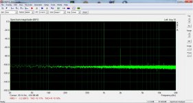
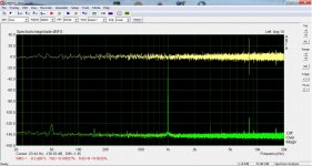
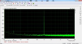
Almost good... I can't find what's causing this high pitched noise. I'm pretty much clueless about it. I'm posting three observations that might tell you something...
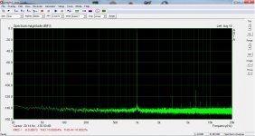
First is that although the frequency will be stable at each session, it is moving from day to day. Before I start modifying it this was between 8 and 11kHz. Now I see it happening between 6 and 8kHz. Second is that the ADC input alone -chip pins floating- is silent (see first pic). If it is connected to anything, the peak appears. By anything I mean buffers, the one on board as well as a number of external circuits, all silent and with low THD. However, everything was sharing the same ground for what matters. The third observation has to do with what you see in the second pic. It is the same channel recorded two times -note the orange line under the green- and above this is the difference of the two measurements. Zero for everything except for the peak! Does this give you any ideas about the nature of this noise?
First is that although the frequency will be stable at each session, it is moving from day to day. Before I start modifying it this was between 8 and 11kHz. Now I see it happening between 6 and 8kHz. Second is that the ADC input alone -chip pins floating- is silent (see first pic). If it is connected to anything, the peak appears. By anything I mean buffers, the one on board as well as a number of external circuits, all silent and with low THD. However, everything was sharing the same ground for what matters. The third observation has to do with what you see in the second pic. It is the same channel recorded two times -note the orange line under the green- and above this is the difference of the two measurements. Zero for everything except for the peak!
Does this give you any ideas about the nature of this noise?Attachments
In the EMU0404 USB, internally generated noise was coupled in on one channel a lot more than the other - and the fix for the noisy channel was to divert signal from a long trace that went past a noisy circuit section by going via a shielded cable. So that issue was very much board layout and trace layout dependent.
E-MU 0404 usb 2.0 and some "artifacts peaks" on left channel
E-MU 0404 usb 2.0 and some "artifacts peaks" on left channel
Last edited:
Thanks for reply!
Although I've seen this thread in the past, I forgot about it. I'll read it again. I'm sure it is a layout problem. Perhaps I was looking in the wrong place. The board is multilayer with ground planes on top and bottom so hard to see a ground problem. The ADC/input and the USB interface sections also seem very straightforward. But the DAC/output section is a mess. I thought that it could not affect the input but you never know with digital circuits. After all, this is the only thing left to check. I'll be back.
Although I've seen this thread in the past, I forgot about it. I'll read it again. I'm sure it is a layout problem. Perhaps I was looking in the wrong place. The board is multilayer with ground planes on top and bottom so hard to see a ground problem. The ADC/input and the USB interface sections also seem very straightforward. But the DAC/output section is a mess. I thought that it could not affect the input but you never know with digital circuits. After all, this is the only thing left to check. I'll be back.
Hi,
About software settings: I tried Behringer ASIO, WDM and ASIO4ALL with all possible sampling frequencies but nothing affects the peak. In particular, with WDM it is possible to set sampling rates as low as 8kHz and what I noticed is that when the sampling rate is not a multiply of 8kHz (11kHz - 22kHz) there are more artifacts. With 8, 16 and 32kHz I get only the "peak". And with 44,1kHz too, even though it's not relevant to 8.
About software settings: I tried Behringer ASIO, WDM and ASIO4ALL with all possible sampling frequencies but nothing affects the peak. In particular, with WDM it is possible to set sampling rates as low as 8kHz and what I noticed is that when the sampling rate is not a multiply of 8kHz (11kHz - 22kHz) there are more artifacts. With 8, 16 and 32kHz I get only the "peak". And with 44,1kHz too, even though it's not relevant to 8.
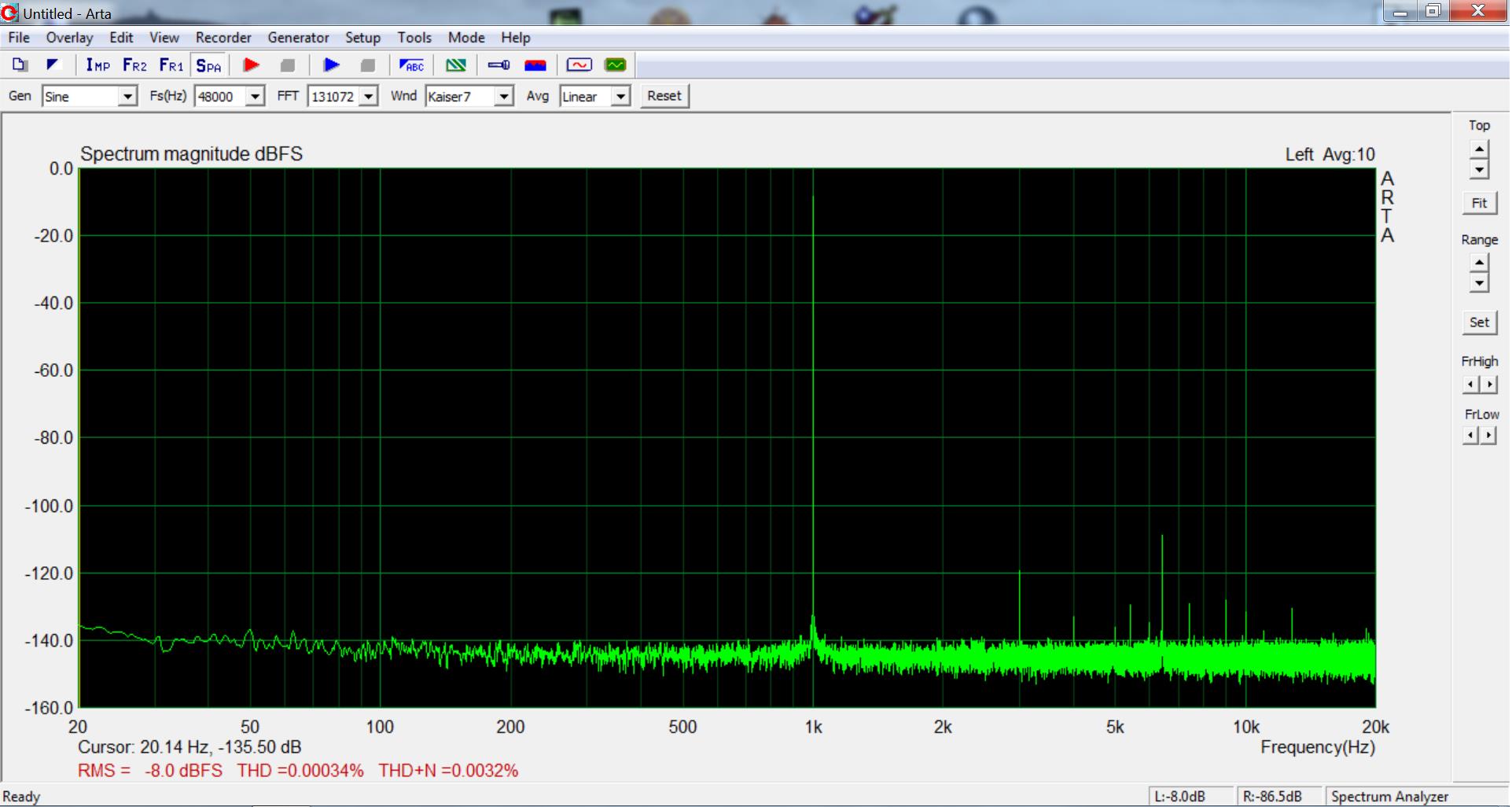
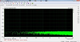
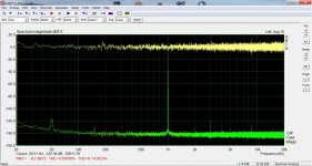
Bingo!  I had the feeling that it had to do with Vcom. The ADC inputs need DC bias at Vcom level but apparently not the actual Vcom, not even buffered. There is a buffer for this on board. It's the half of a RC4580 dual op amp. The other half is also a DC buffer but referenced to a resistance voltage divider from power rail. I couldn't trace where this is going but I simply lifted the other from Vcom and fed it from the voltage divider too. Seems to work! The high frequency peak is still there but it doesn't dominate the spectrum any more.
While working on this, I tried the ADC without DC bias at all. Distortion rises dramatically and it is not about clipping. It seems that the DC bias at half the rail voltage keeps the balance internally in the digital domain. At least this is how I understand it, maybe it's something else. Anyway, all this gave me the idea to replace the fixed voltage divider with a pot to allow trimming "on the fly". I'll check this and also optimize the input capacitors of the SE to BAL converter because this has to do with 50Hz peak.
I had the feeling that it had to do with Vcom. The ADC inputs need DC bias at Vcom level but apparently not the actual Vcom, not even buffered. There is a buffer for this on board. It's the half of a RC4580 dual op amp. The other half is also a DC buffer but referenced to a resistance voltage divider from power rail. I couldn't trace where this is going but I simply lifted the other from Vcom and fed it from the voltage divider too. Seems to work! The high frequency peak is still there but it doesn't dominate the spectrum any more.While working on this, I tried the ADC without DC bias at all. Distortion rises dramatically and it is not about clipping. It seems that the DC bias at half the rail voltage keeps the balance internally in the digital domain. At least this is how I understand it, maybe it's something else. Anyway, all this gave me the idea to replace the fixed voltage divider with a pot to allow trimming "on the fly". I'll check this and also optimize the input capacitors of the SE to BAL converter because this has to do with 50Hz peak.
Attachments

Bingo!
While working on this, I tried the ADC without DC bias at all. Distortion rises dramatically and it is not about clipping. It seems that the DC bias at half the rail voltage keeps the balance internally in the digital domain. At least this is how I understand it, maybe it's something else. Anyway, all this gave me the idea to replace the fixed voltage divider with a pot to allow trimming "on the fly". I'll check this and also optimize the input capacitors of the SE to BAL converter because this has to do with 50Hz peak.
-RNM
There is lots on the UMC204HD here Budget DAC Review: behringer UMC204HD | Audio Science Review (ASR) Forum which probably apply to the UH202 as well.
Sometimes the odd spurs come from the host PC Vbuss or it not being quite strong enough. Check that its at 4.75 or more at the UH202 end of the cable. Or the peak may be crosstalk from the USB communications which are at around an 8 KHz rate but the data modulate the rate so it moves.
It is basically great performance for not much money. For 6X more you get a 10% improvement. For 20X a 15% improvement and for 250X a 15.5% improvement depending on how you value the improvement.
Now the hard part- learning what to make of what you see with this tool.
Thank you all!
@1audio: I came across this thread, it was not all very clear to me but I checked the power supply. From USB Vbus it comes exactly 4,75V but after on board filtration, 4,5V is what all the chips see. I hacked a USB cable and fed the soundcard with external psu. I forced it up to 5,5V real Vcc at the chips but I didn't see any difference.
As I said in the first post, my needs are bellow the average. Even if it was not for the money, the more advanced equipment would simply left unused on the shelf.
Last edited:
...Anyway, all this gave me the idea to replace the fixed voltage divider with a pot to allow trimming "on the fly"...
I tried it. Yes, it does allow direct control on THD but I didn't manage to get any better figures than with the fixed voltage divider. So, an unnecessary complexity. The project is pretty much completed. I'll take some good photos to demonstrate the tweaks. It turned out to be fairly easy!
Attachments
How to do it!
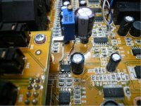
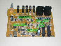
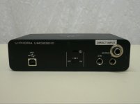
Remove the screws that secure the input jacks in the front panel and the knobs. Remove the rear panel too -another three screws. Then the pcb slides out of the chassis. The photo shows what I have. I'm not aware if there have been any revisions so please compare with yours. The areas of interested are marked. The audio codec (CS4272), the ADC input buffer (AD8694), its coupling capacitors and the Vcom buffer (behind the electrolytic cap). Right in front of that cap is the copper trace that needs to be cut. Three steps to improve performance, each one independent from the others.
Remove the screws that secure the input jacks in the front panel and the knobs. Remove the rear panel too -another three screws. Then the pcb slides out of the chassis. The photo shows what I have. I'm not aware if there have been any revisions so please compare with yours. The areas of interested are marked. The audio codec (CS4272), the ADC input buffer (AD8694), its coupling capacitors and the Vcom buffer (behind the electrolytic cap). Right in front of that cap is the copper trace that needs to be cut. Three steps to improve performance, each one independent from the others.
Attachments
Step #1: Access to ADC input buffer.
Remove the coupling electrolytics and solder wires in their pads. I used cat5 solid core. In the picture, the colored wires are what comes from the mic preamps and the white are what goes to input buffer.

I wired them as shown in the schematic.
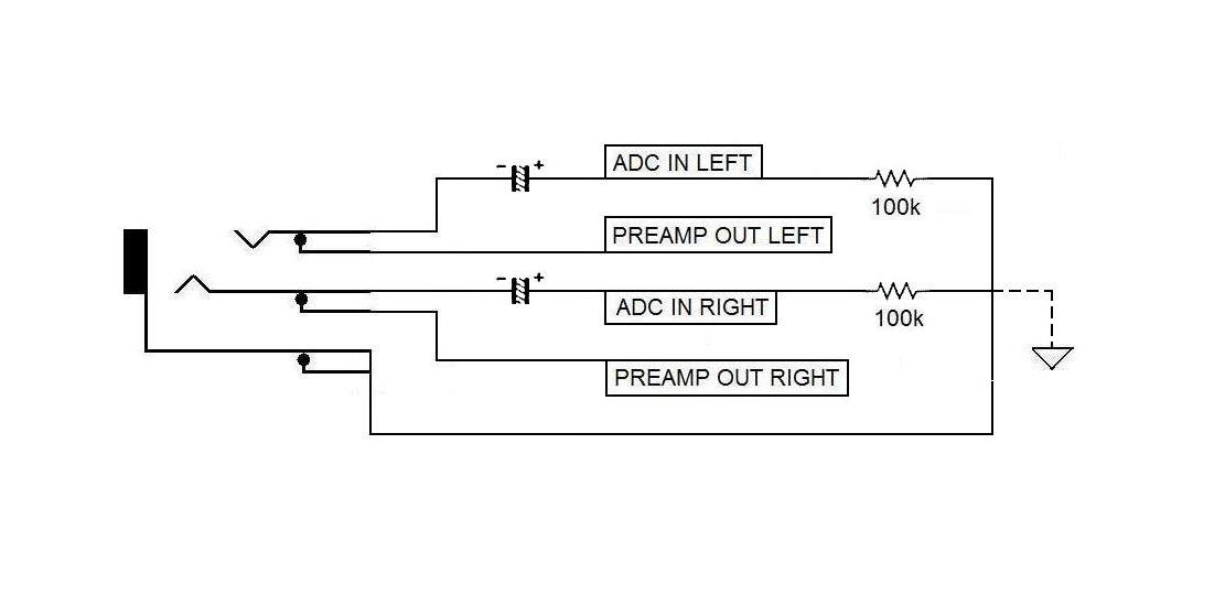
This way when nothing is inserted, the circuit is restored and all front panel inputs and controls are fully functional. When the jack goes in, the mic preamps are bypassed. Please resist the temptation to use audiophile caps. We need at least 10μF in compact size. I used the original 47μF but with polarity reversed. Be sure you do that otherwise distortion and noise go up. The 100k resistors are good to add. The question is what to do with the ground. I think it should be left floating. It makes sense for loop measurements. However, it doesn't seem to have any impact in performance if attached to ground. Finally, I drilled a hole in the rear panel to hold the jack. That's the only sign of the modifications.
Remove the coupling electrolytics and solder wires in their pads. I used cat5 solid core. In the picture, the colored wires are what comes from the mic preamps and the white are what goes to input buffer.
I wired them as shown in the schematic.
This way when nothing is inserted, the circuit is restored and all front panel inputs and controls are fully functional. When the jack goes in, the mic preamps are bypassed. Please resist the temptation to use audiophile caps. We need at least 10μF in compact size. I used the original 47μF but with polarity reversed. Be sure you do that otherwise distortion and noise go up. The 100k resistors are good to add. The question is what to do with the ground. I think it should be left floating. It makes sense for loop measurements. However, it doesn't seem to have any impact in performance if attached to ground. Finally, I drilled a hole in the rear panel to hold the jack. That's the only sign of the modifications.
Attachments

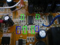
Step #2: Improve ADC input buffer performance.
SMD job! You can do it! I did it with an ordinary soldering iron. And I reviewed it many times the following night in my dreams...
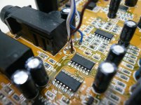
The picture is a close up of the input buffer. The colored frames is what needs to be removed. In blue are the resistors that are in parallel with the ADC inputs -see first post- and they will stay open. Easy! In green are the the op amp's output resistors. We need something there but not the original 1k. The lower the better and I've seen as low as 22ohm in some schematics. I used 91ohm salvaged from another pcb. There won't be a close photo of my smd rework and that's final!
SMD job! You can do it! I did it with an ordinary soldering iron. And I reviewed it many times the following night in my dreams...
The picture is a close up of the input buffer. The colored frames is what needs to be removed. In blue are the resistors that are in parallel with the ADC inputs -see first post- and they will stay open. Easy! In green are the the op amp's output resistors. We need something there but not the original 1k. The lower the better and I've seen as low as 22ohm in some schematics. I used 91ohm salvaged from another pcb. There won't be a close photo of my smd rework and that's final!
Attachments
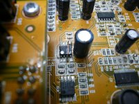
Step #3: Kill the high frequency peak.
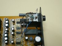
You need a sharp cutter for this. Cut the trace that goes to the Vcom buffer close to pin #5. I cut it at the other side too, close to the ADC. It may not be of any importance though. If you do that make sure you leave intact the decoupling caps at pin #15. Then on the Vcom buffer just bridge pin#5 with pin#3. You should do it with the shortest wire that leans on the op amp, otherwise... noise.
That's all!
PS. Be gentle with the cutter. Although I haven't verified, this is likely a multilayer pcb. Don't go too deep!
Attachments
Last edited:
Very interesting, thanks a lot for sharing! Do I understand correctly there was no active component replacement, only removing/changing resistors and capacitors?
The lowered output resistors - another option would be keeping the existing resistor and soldering a new one on top.
The lowered output resistors - another option would be keeping the existing resistor and soldering a new one on top.
Yes, only 6 smd resistors and 2 electrolytic capacitors. And a few wires. You are right about paralleling the output resistors. Another thing I did in my preliminary tests was to use through hole resistors directly from the op amp -solered at pins 1,7,8,14- to the ADC - right on the antialiasing capacitors. No noise problems. Unfortunately, I haven't kept a photo of that.
- Home
- Design & Build
- Equipment & Tools
- Behringer UMC 202HD for measurements