1+!Fantastic. How about -150dB? Thanks a lot for your incredible support.
Plus automatic preset values from last valid RTA distortion measurement?
Well, maybe you and John could actually team up to implement your scheme into REW?
There is a very big difference between the wide and deep knowledge/experience you have acquired throughout the many years vs. the very narrow specific focus I learned in the single year of my distortion project.
True, but don't undermine your efforts.
As first step I tried to generate a waveform that has a 1k fundamental at 0dBV and a -60dBV 2nd with a defined phase difference of -90deg and see it the analyzer recognizes that.
Defining the waveform is easy, but I can't make anything from the phase results (amplitude results seen OK). Used the FFT analyzer but the phase info looks nonsensical. See relevant data attached.
Might have an issue with triggering of the FFT but it's hard to find out what exactly is going on...
Jan
Attachments
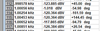
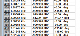
Are the two screenshots results of one FFT? They have a different bin (2Hz vs. 4Hz).
If so, the result looks like the 2nd harmonic has not been phase-shifted. The fundamental is at -55deg. The H2 is twice as fast. Should be 2 * fundamental shift + initial shift. You have it exactly at 2 * fundament = -55 * 2 = -110deg. But again, it does not look like the two values are from the same FFT run.
Can you configure your FFT to fit the sampling rate, so that you hit integer Hz in FFT? I am using 48k for 48kHz sampling rate, each bin is exactly 1 Hz. 96k, 192k, etc. all would yield a bin with 1,000Hz center exactly.
Of course the method requires that DAC and DAC run synchronously, so that 1kHz by the DAC gets sampled as 1kHz by the ADC. I assume it holds for your PA.
Made some progress.
I generated a couple of twin-tone multitones, and measured the phase shifts*. Got these results:
test tone pair: FFT:
1k 0dBV 0° -90°
2k -60dBV +90° -1°
1k 0dBV 0° -90°
2k -60dBV -90° +179°
1k -6dBV 0° -90°
2k -80dBV +45° -46°
It seems that the phase relationships are correct, even if the absolute values are not, but that may be a trigger artifact.
Comments?
Q: I set the FFT length to Auto. Other choices were the familiar 4096 ... 32768. Auto is supposed to adjust itself to the signal record length. I wonder if Auto can generate non-power-of-two FFT lengths. In theory it should I think.
Maybe change the two tone frequencies to adapt to the FFT length to be completely synchronous?
*The purpose of this is to measure the amplitude and phase shift of a 2nd harmonic in a loop-back self-test result and generate a new test tone with a 2nd harmonic that has the the same amplitude but opposite phase, compensating for the self-distortion. IOW, generate a test tone that, ideally, shows zero distortion in loop-back.
Jan
Last edited:
There's nothing wrong with the principle, though "zero" may be a challenge*The purpose of this is to measure the amplitude and phase shift of a 2nd harmonic in a loop-back self-test result and generate a new test tone with a 2nd harmonic that has the the same amplitude but opposite phase, compensating for the self-distortion. IOW, generate a test tone that, ideally, shows zero distortion in loop-back.
. Here it is done on a cheap 16-bit soundcard, for the second image an opposite phase 2nd harmonic was added to the test signal, dropping the level of the distortion component by 30 dB.

There's nothing wrong with the principle, though "zero" may be a challenge
View attachment 774268
View attachment 774269
Well I would be very happy with a 30dB reduction!
How did you generate that opposite 2nd, sound card digital generator?
Jan
Yup.How did you generate that opposite 2nd, sound card digital generator?

The purpose of this is to measure the amplitude and phase shift of a 2nd harmonic in a loop-back self-test result and generate a new test tone with a 2nd harmonic that has the the same amplitude but opposite phase, compensating for the self-distortion. IOW, generate a test tone that, ideally, shows zero distortion in loop-back.
That is why I call joint-sides calibration applied to DAC side.
FFT (at any time, triggering is irrelevant) will tell you fundamental and harmonics phase + amplitude.
Harmonics amplitudes:
a) scale harmonics level linearly to your fundamental level so that the relative amplitude fundamental vs. harmonic is same. E.g. generated -3dB fundamental, recorded -6dB fundamental, recorded -100dB H2 -> pre-distorting H2 on DAC side will be -97dB.
Harmonics phases:
a) Calculate time offset (T) of the measured fundamental phase to time zero when fundamental was at 0 deg.
b) Calculate how much phase shift (fi_offset) each harmonic accumulated during that time T.
c) Subtract fi_offset from your measured harmonic phase, yielding fi0. That is the harmonic phase at time zero, when fundamental was at 0deg. This is how much your harmonic would measure if your FFT was triggered at time zero when fundamental was at 0deg.
d) Generate your compensated (pre-distorted) signal with fundamental starting at 0deg and harmonics starting at their inverse fi0 (fi0 - 180deg), so that each will cancel out with the corresponding harmonic generated by the loopback chain.
The very same principle holds for dual-tone, the time offset is to the moment BOTH fundamentals were at 0 deg. Finding such time for any general multitone is also possible, IMO.
OK, I get that. I think. But wouldn't any 2nd harmonic distortion necessarily be either at 0deg or 180 deg wrt the fundamental? (assuming flat response).
Jan
That depends on the distortion mechanisms, the overall component if there is more than one contributor could have any phase depending on the relative amplitudes of the contributing components.But wouldn't any 2nd harmonic distortion necessarily be either at 0deg or 180 deg wrt the fundamental? (assuming flat response).
That depends on the distortion mechanisms, the overall component if there is more than one contributor could have any phase depending on the relative amplitudes of the contributing components.
But isn't a 2nd always the result of compressive or expansive gain changes through a cycle that are symmetrical, and thus always in phase/opposite phase? If it is shifted and/or not symmetrical, it should be another harmonic component or a combination of several, no?
Just thinking out loud really.
Jan
Distortion means the amplifier's departure from a perfectly linear transfer function. It is surprising nobody analyses distortion by precisely determining an amplifier's transfer polynomial to as higher a degree as experimentally possible. Such a polynomial would give a lot of insight of what is done with individual harmonics.
A couple of thoughts re phase-shifted harmonic distortion---intuition only, unanalyzed...
The distortion might be phase-shifted by the amplifer's internal gain rolloff. Another maybe more likely mechanism might be non-linear junction capacitance currents which might be inherently in quadrature with the applied signal.
The distortion might be phase-shifted by the amplifer's internal gain rolloff. Another maybe more likely mechanism might be non-linear junction capacitance currents which might be inherently in quadrature with the applied signal.
edbarx: The transfer polynomial method was used for the initial version of the harmonic distortion compensation, e.g. https://www.diyaudio.com/forums/equ...ensation-measurement-setup-2.html#post5584029 It's quite simple to calculate the polynomial coeffs to any length by curve fitting. For compensation purposes the transfer polynomial -> inverse transfer polynomial did not work satisfactorily since it was unable to clean all harmonics reliably. Subtracting individual harmonics separately yields much better consistent results.
But again, finding the polynomial is quite simple - the method is described in the linked post - curve-fit samples of exact sine multiplied by the polynomial to measured samples, the curve-fitting function will directly yield searched-for coeffs which provide the best fit. Swapping the samples generates inverse transfer polynomial used for pre-distorting the generated signal.
But again, finding the polynomial is quite simple - the method is described in the linked post - curve-fit samples of exact sine multiplied by the polynomial to measured samples, the curve-fitting function will directly yield searched-for coeffs which provide the best fit. Swapping the samples generates inverse transfer polynomial used for pre-distorting the generated signal.
Distortion means the amplifier's departure from a perfectly linear transfer function. It is surprising nobody analyses distortion by precisely determining an amplifier's transfer polynomial to as higher a degree as experimentally possible. Such a polynomial would give a lot of insight of what is done with individual harmonics.
Volterra and Wiener theories of non-linear systems were often used in this context (means for weakly non-linear systems),
see for example in:
P. Wambacq and W. Sansen, Distortion Analysis of Analog integrated Circuits. Kluwer Bosten, 1998, 60 - 115
- Status
- This old topic is closed. If you want to reopen this topic, contact a moderator using the "Report Post" button.
- Home
- Design & Build
- Equipment & Tools
- Distortion analysis - a thought experiment