Hi.
I want build an ESR meter from scratch.
I came across a tutorial on
Simple ESR Meter Circuit | Homemade Circuit Projects
where it says that "The transformer is built over any ferrite ring, using any thin magnet wire with the shown number of turns". (20 turns on one side and 5 turns on the other).
I took out an induction coil from a scrapped computer PSU, unturned the wires from the ferrite ring and put them back on with the indicated number of turns. Then I checked it for continuity and both coils were shorted. The isolating enamel had broken off the wire somewhere...
Then I went the easiest way and pulled to wires from a balanced cable (like the ones used in i.e. audio consoles) and wrapped these around the ferrite ring. I haven't installed this "component" into the circuit, yet.
Would it work?
Is it possible to paint the original copper wire (the one with broken off isolation) with fingernail lacquer?
Thanks for you replies.
I took out an induction coil from a scrapped computer PSU, unturned the wires
from the ferrite ring and put them back on with the indicated number of turns.
Then I checked it for continuity and both coils were shorted.
You can just use standard insulated wire instead.
The advice Rayma gave you is good, if you want to go on with this particular project.
The information given on that site is, let's say, weak: the first circuit will definitely not work, and you will be lucky if the one with the opamp does: operating a 741 on 5V is asking for trouble, and the statement "any ferrite ring will work" seems optimistic.
I can understand that you have difficulties sourcing components, but if possible, you should look for a better, more deterministic alternative.
I think that equally cheap, yet half-workable alternatives exist.
None will actually measure the ESR, but the magnitude of the impedance should be sufficient for basic troubleshooting purposes
OF COURSE they will read "shorted"."The transformer is built over any ferrite ring, using any thin magnet wire with the shown number of turns". (20 turns on one side and 5 turns on the other).
I took out an induction coil from a scrapped computer PSU, unturned the wires from the ferrite ring and put them back on with the indicated number of turns. Then I checked it for continuity and both coils were shorted.
Resistance of such a short piece of wire (10cm or less) is, say, 0.01 ohm or so.
ANY wire that short will measure the same, no matter what the insulation.
No it has notThe isolating enamel had broken off the wire somewhere...
")
EDIT:
Just checked the ESR meter project.
It has gross errors which make me doubt its effectiveness or even that it works at all.
such as:
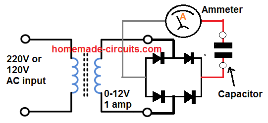
It rectifies 12VAC, applies the resultant DC voltage to capacitor and (tries to) measure DC current through it
Of course, capacitor will charge to peak voltage and stay there; so an initial (quite high but very short) current peak, then nothing.
Ok, maybe a few uA loss.
How/Why would that give any ESR indication at all is beyond me.
The application circuit
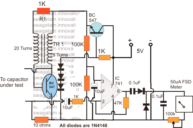
does slightly better (at least in theory) by applying "high frequency audio" to capacitor and measuring current through it , as voltage developed across a 10 ohm resistor.
Nice in theory, terrible implementation:
* waveform is unknown, although being a relaxation oscillator (sort of) waveform is guaranteed to be wonky.
* voltage is also known, but because of the inductive load I expect somewhat high peaks, definitely higher than 5V, at least unloaded.
* oscillator drives capacitor straight up; not sure it will keep oscillating under such a heavy load (tens of ohms)
* the meter rectifier is wrong, as is it´s a half wave rectifier and the second diode does nothing.
Unidirectional current will charge .1uF capacitor to some peak voltage and stay there, being slooowly discharged by the meter.
Second diode should be moved to the left of the first one, so we have a full wave doubler/rectifier.
A minor matter: describing the Op Amp as:
while it actually is an inverting voltage amplifier.An opamp can also be seen attached with the above low voltage high frequency feed and is configured as a current amplifier.
Oh well
Last edited:
the first circuit will definitely not work, and you will be lucky if the one
with the opamp does: operating a 741 on 5V is asking for trouble
The 741 is rated for 20V minimum, not 5V. I would use a 5V op amp.
operating a 741 on 5V is asking for trouble
Operating a 741 full stop is asking for trouble [emoji23]
741 Op Amps were for decades the mainstay for 9V battery operated pedals (as in MXR Distortion Plus , Phasers, Equalizers, and countless others) .The 741 is rated for 20V minimum, not 5V. I would use a 5V op amp.

Maybe an "undocumented feature" but valid and widely known (and used).
That said, 5V operation IS way too low.
But don´t worry
, clearly circuit designer never ever built, let alone tested it Only a geek would think that.Operating a 741 full stop is asking for trouble
Oh .... wait !!!!
You should read some Audio History: 741 was a Godsend when it appeared.
Usable everywhere, specially in Instrumentation but so flexible that it could also be used in Audio,although not specifically designed for it.
Of course, the simplest Mathematical operation is multiplying by a fixed number, and in the Audio realm it means "amplification"; the most trivial application.
Real Pro Audio stuff was designed around it, from complex Graphic and Parametric equalizers to BBC issued
Power amplifiers (HH amps) to Mic Preamps to you-name-it .Of course, and that was to be expected, Technology advanced and it was surpassed by others ,,, many years later that is.
As of the application shown above, 47X amplification to drive a meter, it´s way more than adequate.
Only a geek would think that.
Oh .... wait !!!!
You should read some Audio History: 741 was a Godsend when it appeared.
Oh sure and I played with them back in the 80s since it's what I had on hand... But they have problems and there are much better opamps available these days. Sure if a 741 is all you can lay hands on, it might do. But why suffer when there are much better options cheaply and easily available...
The 741 is not the only opamp I have on hand. I also have several NE5534, OPA134, TL071, 2003P (all sigle opamps). Which one would you suggest?
When I first saw the 5V in order to operate an LM741, it sounded funny to me, too.
I could rise the voltage to 9VDC, but I have no clue as to what to consider, either in the circuit as well as the ESR calculations goes.
What if I use the original copper wire that I took of the ferrite ring and apply some thick nail polish? That is the next best thing I have on hand for this purpose.
This project has most of the building blocks required for an ESR meter; just a few cosmetic arrangements are required:
My take on the winding's phase-finder (AKA "Phasedots tester")

The stimulus generation section U1 U2 is basically OK, the frequency could be increased, and the test current adjusted, but that's no big deal.
The preamplifier U3 can also be used, but without the clipping diodes.
The phase detector U4 is not required, and can simply be ignored, or converted into another amplifier.
Finally, a diode detector would drive the meter
As the circuit has already been tested in its previous form, the new version could be made to work with a minimum work of debugging
My take on the winding's phase-finder (AKA "Phasedots tester")
The stimulus generation section U1 U2 is basically OK, the frequency could be increased, and the test current adjusted, but that's no big deal.
The preamplifier U3 can also be used, but without the clipping diodes.
The phase detector U4 is not required, and can simply be ignored, or converted into another amplifier.
Finally, a diode detector would drive the meter
As the circuit has already been tested in its previous form, the new version could be made to work with a minimum work of debugging
Phantom, if you indicate your preferences, I will provide an adapted schematic for the phase tester, and I will even breadboard it, to check that it performs as intended.
It will not be more complicated than your initial choice (1 cheap, common IC required), and it will operate in a much more deterministic manner: it will even provide semi-calibrated results if you want.
What I mainly need to know, is your preferred indicating device: a 50µA galvanometer, a multimeter, or else?
I think that such a project might help other members, and is worth pursuing.
If you find another alternative, you can submit it: we will check its sanity.
Thank you very much, I will most certainly accept your offer. What I need is not so much a phase tester but ESR meter. And I don't have a clue if both meters are basically the same...
Here is what I have on hand:
A digital multi-meter with 2000µ / 20m / 200m / 10 DC Ampere on its scale.
Some analog meters but these have a range up to 100 DC Ampere, that's probably way to much for a few µA squeezed on a 1.5 inch scale...
A regulable DC power supply, based on the LM317 adjustable regulator.
Thanks again for taking on the herculean task of developing a schematic.
Phantombox
The 741 is rated for 20V minimum, not 5V. ...
An incomplete specification. Perhaps to promote sales of later "low voltage" chips.
The turning-point is 7V. Above that all the guts get proper current. There is considerable internal drop in a '741 but you still get some output swing.
Below 7V the guts starve for current, gain and GBW fall off quick, and the fairly constant voltage losses leave very little output swing.
Still for a utility audio oscillator, it may do fine even at 5V. If it does not do all the spec-sheet says, you have no complaint because you did violate the "minimum".
Thousands of guitar pedals showed that it did in fact "work", at some useful level, with 9V batts fading to 6V.
Agree that page's "ideas" are maybe not the best, maybe not good.
While looking at the Alan Wolke design, I found a link to another project esr meter – awsh.org. What do you think of that?
- Status
- This old topic is closed. If you want to reopen this topic, contact a moderator using the "Report Post" button.
- Home
- Design & Build
- Equipment & Tools
- Oscillator coil with common wires?