The modal analysis hardware has made some more progress lately, so I thought I'd start a new thread to post the updates. There have been a number of upgrades and improvements in this version of the hammer and it's about ready for a market test on eBay.
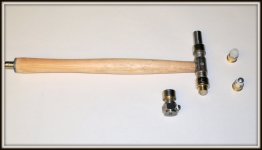
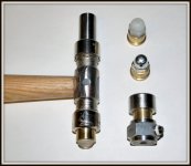
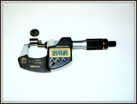
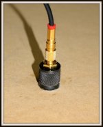
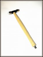
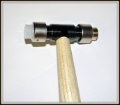
The photos show one of the latest versions of the hammer and its different tips. The tips include a choice of rubber, Nylon, or stainless steel. There is also a detachable added mass for the back of the hammer to improve the signal output of the soft rubber tip when needed.
The other attachable item in the photo (not included with the hammer) is a Bruel & Kjaer 8200 force transducer that can be mounted on the front of the hammer and behind the selected tip. This adds an extra comparison calibration for the hammer's installed force transducer.
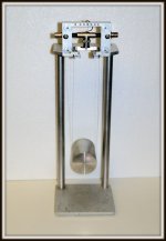
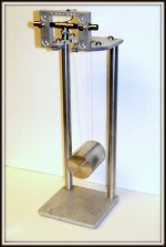
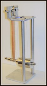
The calibration test stand consists of a cylindrical test mass supported on thin Inconel wires. The mass has a calibrated B&K 4384 accelerometer installed on its backside as a further calibration point.
The accelerometer design and testing is also close to the finish line and should be ready soon as a compliment to the modal hammer. The plan is to offer the pair as an entry level front end set of transducers for those who want to move up to the next level of speaker enclosure testing and evaluation.
The photos show one of the latest versions of the hammer and its different tips. The tips include a choice of rubber, Nylon, or stainless steel. There is also a detachable added mass for the back of the hammer to improve the signal output of the soft rubber tip when needed.
The other attachable item in the photo (not included with the hammer) is a Bruel & Kjaer 8200 force transducer that can be mounted on the front of the hammer and behind the selected tip. This adds an extra comparison calibration for the hammer's installed force transducer.
The calibration test stand consists of a cylindrical test mass supported on thin Inconel wires. The mass has a calibrated B&K 4384 accelerometer installed on its backside as a further calibration point.
The accelerometer design and testing is also close to the finish line and should be ready soon as a compliment to the modal hammer. The plan is to offer the pair as an entry level front end set of transducers for those who want to move up to the next level of speaker enclosure testing and evaluation.
Attachments
Last edited:
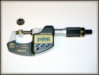
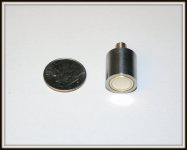
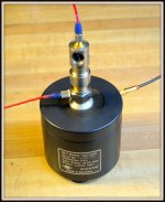
I think I've finally arrived at the last accelerometer design and a working prototype for the time being. This one weighs in at 11 grams and should work well with any speaker enclosure that's out there. Typically an accelerometer should not weigh more than 10% of the structure that is being tested. That would limit this ones practical use to a panel weighing no less than about 4 oz. I don't think there will be any mass loading problems with most enclosure tests.
I've just finished the final assembly tonight so the full characterization won't be done for a couple of days. The basic design incorporates a magnetic base for attachment to any ferromagnetic structure. Otherwise the attachment can be done with things like super glue, double backed tape, or microcrystaline wax. I'm a big wax fan! It's easy to use, very tenacious, and cleans up easily.
The photos indicate the size of the device.
Attachments
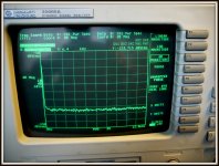
Some of the measurements that I've been playing with lately are transfer functions on the accelerometers. Using an HP 35665A Digital Signal Analyzer (DSA) I'm able to set up a network analyzer and do frequency response plots. Single point measurements using the B&K 2970 Sensitivity Comparator is useful when writing specs for the devices, but the frequency response plots hold much more information about overall performance.
Utilizing the DSA's random white noise signal source and running it into a B&K 2706 amplifier, a B&K 4810 shaker can be used as a stimulus. The response is then generated using a B&K 8200 force transducer attached to the shaker along with the accelerometer to be tested coupled to the 8200.
I'm interested in how flat the frequency response plots are with the accelerometers that I'm building. The range needed to test most speaker enclosure panels would be about 10 Hz to 12 kHz. The 8200 is a flat line in that range, so any deviation from flat will be the transfer function of my devices.
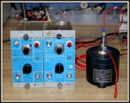
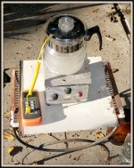
Here's a quick update on the accelerometer testing. The photos show the mini-shaker with the 8200 force transducer mounted to the table and the accelerometer mounted on top of it. The accelerometer has a magnetic base built into it for easy attachment to ferromagnetic surfaces. I machined a steel mounting plate to fit onto the 8200 for these tests. Wax or glue can also be used as an attachment option.
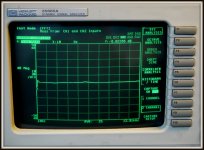
The DSA is set to do a frequency response plot from 10 Hz to ~ 12 kHz. The scope photo shows the random noise signal coming from each transducer. The response is well within what would be needed to do a simple modal analysis on a typical speaker enclosure.
The charge amplifiers are from eBay and also readily available from a source here on this forum.
Attachments
I've gotten to the point where the modal hammer's load cell design is built as a discrete component. This allows each transducer to be tested as a frequency response transfer function without having to build a full hammer assembly for testing. Previously I had to build a complete hammer for these measurements.
The photo shows the setup for doing these tests. The same 8200 force transducer is mounted onto the table of the 4810 mini shaker that's used for testing the accelerometers. I've modified one of the modal hammer heads to allow it to be mounted on top of the 8200 the same way as an accelerometer would be mounted. The load cell can be inserted into the testing head and be preloaded for the measurement.
When a load cell is deemed worthy, it's transferred and permanently sealed into a finished hammer. Further measurement and calibration is then done using the pendulum impulse apparatus that was shown in a previous post.
Attachments
I thought it might be useful to re-post some info from a previous thread that I started some time ago. That thread was also about modal testing but devolved into posts about construction materials. I'll confess to having helped the thread slide off the rails once it was clear that my initial information was becoming obfuscated.
In another attempt to march a straight course I'm posting this information about modal hammers that was acquired from the Endevco site. This is all their information, so I hope that I haven't infringed on anything that may have any copy-write claims. The link to their webpage doesn't work. I haven't tampered with the content.
---------------------------------------------------------------------------------------------------------------
[FONT=Arial, Helvetica, sans-serif]Selecting the correct modal hammer [/FONT]
[FONT=Arial, Helvetica, sans-serif]
Question
I have to carry out a modal test in order to identify the dynamic properties of my test specimen. Is there any rule that could help me in selecting the right modal hammer with respect to e.g. specimen size and mass?
Answer
There is no fixed rule that would provide a clear indication which modal hammer is the most appropriate one to carry out the test. Although there is a set of aspects/factors that has to be considered before the choice of modal hammer is made.
Factor 1. Frequency bandwidth
Modal testing carried out with a modal hammer is based on providing the impact to the specimen, resulting in vibration over a broad frequency bandwidth. The width of frequency band of excited vibration depends on the impact duration. The shorter the pulse width, the higher the frequencies being excited. The impact duration can be changed by mounting special hammer tips of different stiffness. The different hammer tips allow various frequency bandwidths to be excited with the modal hammer, impacting the specimen with the same energy (the softer the hammer tip, the longer pulse, the narrower the excited frequency bandwidth).
[/FONT]
[FONT=Arial, Helvetica, sans-serif] [/FONT][FONT=Arial, Helvetica, sans-serif]
The final duration of the pulse, in certain cases, may also depend on the stiffness of the specimen that is being impacted. It is also important to remember that when a hard tip is used, the energy of the impact is being distributed over a wide frequency bandwidth, which means the power spectral density of the excitation may be low in certain cases, too low, to excite specimen vibration modes/resonances. In such cases we may try to hit the structure under test harder by taking a more robust swing or increasing the mass of the hammer by adding a head extender. Unfortunately this approach may also increase the risk of saturating the IEPE force transducer. Therefore, in certain cases, the change to the hammer model featuring a larger measurement range may be considered. Another solution is the application of a softer tip. This results in the energy of the impact being concentrated at lower frequencies (discussed in follow on section).
Factor 2. Amplitude of the pulse
The type of tip being used strongly influences the shape of the impact pulse - not only its duration but also its amplitude. Below graphic shows the force pulses of equal energy applied to the specimen having different hammer tips.

Usage of a hard hammer tip may imply usage of a modal hammer featuring a high measurement range force transducer. The lower measurement range force transducer may limit the usage of the hard hammer tips, which will not allow exciting vibration of high frequencies.
Factor 3. Mass of the hammer, Energy of the impact
The variety of shapes and masses, as well other properties of tested objects, like stiffness or damping require a variety of force pulses of different parameters for proper excitation. In general small compact objects tend to feature higher resonance frequencies and require lower energies of impact to be excited compared to large objects. Therefore in order to excite a small structure most likely at low energy, a short lasting force will be needed. Such a pulse can be provided with small and medium hammers like Endevco 2301 or hammers from Endevco 2302 family. Larger structures will require higher energy impact, most likely concentrated in a low frequency bandwidth. In such cases, larger hammers like Endevco 2303 2304 2305 with soft or medium stiffness tips, will be more appropriate to provide the force pulse excitation desired.
Factor 4. Tests repeatability
To be able to provide the mechanical excitation, of a desired parameter, we need to choose between different force measurement ranges, hammer tips and hammer masses. In practice during modal testing the hammer impacts performed by the operator may differ from one to the other, in terms of impact energy and frequency bandwidth of excited vibrations, as well as the angle of impact. Because of that a common practice is to average several results obtained in particular measurements. The objective is to obtain good quality, repeatable data results obtained in the particular measurements, being as similar as possible.
Modal hammers are available in number of different masses so the hammer operator can provide force pulses of different energies without the necessity of taking big swings during which it is difficult to control the force and angle at which the hammer tip impacts the structure.
[/FONT]
In another attempt to march a straight course I'm posting this information about modal hammers that was acquired from the Endevco site. This is all their information, so I hope that I haven't infringed on anything that may have any copy-write claims. The link to their webpage doesn't work. I haven't tampered with the content.
---------------------------------------------------------------------------------------------------------------
[FONT=Arial, Helvetica, sans-serif]Selecting the correct modal hammer [/FONT]
[FONT=Arial, Helvetica, sans-serif]
Question
I have to carry out a modal test in order to identify the dynamic properties of my test specimen. Is there any rule that could help me in selecting the right modal hammer with respect to e.g. specimen size and mass?
Answer
There is no fixed rule that would provide a clear indication which modal hammer is the most appropriate one to carry out the test. Although there is a set of aspects/factors that has to be considered before the choice of modal hammer is made.
Factor 1. Frequency bandwidth
Modal testing carried out with a modal hammer is based on providing the impact to the specimen, resulting in vibration over a broad frequency bandwidth. The width of frequency band of excited vibration depends on the impact duration. The shorter the pulse width, the higher the frequencies being excited. The impact duration can be changed by mounting special hammer tips of different stiffness. The different hammer tips allow various frequency bandwidths to be excited with the modal hammer, impacting the specimen with the same energy (the softer the hammer tip, the longer pulse, the narrower the excited frequency bandwidth).
[/FONT]
[FONT=Arial, Helvetica, sans-serif]
[/FONT][FONT=Arial, Helvetica, sans-serif] The final duration of the pulse, in certain cases, may also depend on the stiffness of the specimen that is being impacted. It is also important to remember that when a hard tip is used, the energy of the impact is being distributed over a wide frequency bandwidth, which means the power spectral density of the excitation may be low in certain cases, too low, to excite specimen vibration modes/resonances. In such cases we may try to hit the structure under test harder by taking a more robust swing or increasing the mass of the hammer by adding a head extender. Unfortunately this approach may also increase the risk of saturating the IEPE force transducer. Therefore, in certain cases, the change to the hammer model featuring a larger measurement range may be considered. Another solution is the application of a softer tip. This results in the energy of the impact being concentrated at lower frequencies (discussed in follow on section).
Factor 2. Amplitude of the pulse
The type of tip being used strongly influences the shape of the impact pulse - not only its duration but also its amplitude. Below graphic shows the force pulses of equal energy applied to the specimen having different hammer tips.
Usage of a hard hammer tip may imply usage of a modal hammer featuring a high measurement range force transducer. The lower measurement range force transducer may limit the usage of the hard hammer tips, which will not allow exciting vibration of high frequencies.
Factor 3. Mass of the hammer, Energy of the impact
The variety of shapes and masses, as well other properties of tested objects, like stiffness or damping require a variety of force pulses of different parameters for proper excitation. In general small compact objects tend to feature higher resonance frequencies and require lower energies of impact to be excited compared to large objects. Therefore in order to excite a small structure most likely at low energy, a short lasting force will be needed. Such a pulse can be provided with small and medium hammers like Endevco 2301 or hammers from Endevco 2302 family. Larger structures will require higher energy impact, most likely concentrated in a low frequency bandwidth. In such cases, larger hammers like Endevco 2303 2304 2305 with soft or medium stiffness tips, will be more appropriate to provide the force pulse excitation desired.
Factor 4. Tests repeatability
To be able to provide the mechanical excitation, of a desired parameter, we need to choose between different force measurement ranges, hammer tips and hammer masses. In practice during modal testing the hammer impacts performed by the operator may differ from one to the other, in terms of impact energy and frequency bandwidth of excited vibrations, as well as the angle of impact. Because of that a common practice is to average several results obtained in particular measurements. The objective is to obtain good quality, repeatable data results obtained in the particular measurements, being as similar as possible.
Modal hammers are available in number of different masses so the hammer operator can provide force pulses of different energies without the necessity of taking big swings during which it is difficult to control the force and angle at which the hammer tip impacts the structure.
[/FONT]
Modal analysis is usually considered to be a frequency domain method for determining the mode shapes of structures. Time domain modal analysis methods can also be used to evaluate response data from known excitation sources. The data from known inputs can often produce better analysis accuracy.
The time domain method can have advantages over the frequency domain method when applied in the audio world. This is because the time domain doesn't require the full assembly of a loudspeaker enclosure with the drivers installed and driven to produce the modal stimulus. The averaged value from a few simple taps of an instrumented hammer, implemented with the proper hammer tip, can produce all of the necessary frequencies needed to construct a surface plot of a vibrating enclosure panel.
By using the roving hammer method of excitation along with a fixed position accelerometer, simple spreadsheet software can be used for the detection and reduction of unwanted extraneous resonances from an enclosure.
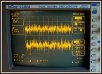
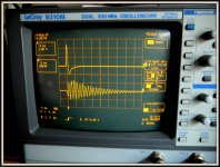
There was a question earlier about the S/N level when the modal hammer and accelerometer were plugged straight into an average DSO with 1 Meg ohm inputs. One photo show the noise floor of the accelerometer when connected straight into ch1 of the hp DSA. The device was left just hanging in the air on its cable. As can be seen the noise floor of the device is below -120 dBVrms out to at least 12.8 kHz.
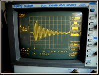
The screen shots of the LeCroy scope were also taken with the outputs of the modal hammer and the accelerometer connected straight into ch1 and ch2. The signals were produced using the accelerometer attached with microcrystaline wax to the center of a 1 sq. ft. 3/4" MDF in a quasi free-free arrangement with the panel laying on top of a piece of egg-crate foam. The top trace is the output of the hammer's tap and lower trace is the accelerometer's response.
This is a reasonable demonstration that the modal approach to doing entry level speaker enclosure testing can be done without having to over invest in some of the more expensive hardware and instrumentation typically used for these measurements. More hardware and software can be added as the testing advances according to ones needs and desires.
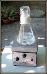
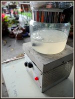
The photo of the flask sitting on the hotplate shows the method I used to put a hot black oxide coating on the accelerometer body. Most of the literature on this method claims that the process of doing the "hot" coating at home should never be attempted unless you're a thrill seeker with a death-wish. I'll allow that there's some merit to that advise.
One of the photos shows the finished accelerometer mounted on the MDF. I'll have to say that I think the coating came out pretty good as far as I can tell using my one remaining eye.
The screen shots of the LeCroy scope were also taken with the outputs of the modal hammer and the accelerometer connected straight into ch1 and ch2. The signals were produced using the accelerometer attached with microcrystaline wax to the center of a 1 sq. ft. 3/4" MDF in a quasi free-free arrangement with the panel laying on top of a piece of egg-crate foam. The top trace is the output of the hammer's tap and lower trace is the accelerometer's response.
This is a reasonable demonstration that the modal approach to doing entry level speaker enclosure testing can be done without having to over invest in some of the more expensive hardware and instrumentation typically used for these measurements. More hardware and software can be added as the testing advances according to ones needs and desires.
The photo of the flask sitting on the hotplate shows the method I used to put a hot black oxide coating on the accelerometer body. Most of the literature on this method claims that the process of doing the "hot" coating at home should never be attempted unless you're a thrill seeker with a death-wish. I'll allow that there's some merit to that advise.
One of the photos shows the finished accelerometer mounted on the MDF. I'll have to say that I think the coating came out pretty good as far as I can tell using my one remaining eye.
Attachments
After actually surviving the hot black oxide coating experiment with the accelerometer bodies, I decides to take it up a notch and try coating one of the modal hammer heads. The jeweler's mallets that I'm using to make the instrumented hammers with comes with a nickel plating for the metal finish. I thought it would be interesting to see how it would look with the black finish. This would match the accelerometers and would lend it the gravitas of the Bruel and Kjaer 8207 instrument. I originally thought that I might have to offer some level of apology for the wooden handle on my hammer until I saw the B&K offering. They get $2380.00 for theirs. Mine will be bargain priced if it ever gets to market.
The photos show the evening's results using the new coating "processor" that I pilfered from a kitchen cabinet. It works great and has the capacity to do larger stuff that I have plans for further down the line.
The photos show the evening's results using the new coating "processor" that I pilfered from a kitchen cabinet. It works great and has the capacity to do larger stuff that I have plans for further down the line.
Attachments
I thought that it might be interesting to extend the concept of time domain modal analysis using a simple Excel plot of a speaker panel's fundamental resonance. The plot shows what a set of 24 stimulus/response points might look like using the roving hammer technique. Of course this is only a first approximation model of what the actual test outcome would be, but it may still be instructive for anyone following this thread. There are no metrics applied to this plot other than a scale with no specific dimension.
Well, it looks as though I'll have to turn this plot file into an image file so that it can be uploaded. I'll work on that.

Well, it looks as though I'll have to turn this plot file into an image file so that it can be uploaded. I'll work on that.
Last edited:
- Status
- This old topic is closed. If you want to reopen this topic, contact a moderator using the "Report Post" button.
- Home
- Design & Build
- Equipment & Tools
- Modal Testing Speaker Enclosures