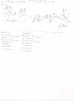
Some time ago I decided to build a low distortion oscillator for amplifier testing.After some research on the internet, I decided to try John Linsley Hood's design (Wireless World ,May 1981) due to its simplicity and good performance.The original article can be found here:http://www.keith-snook.info/wireles...e oscillator with low harmonic distortion.pdf
Construction:
This design calls for the use of an optocoupler as the main AGC element.
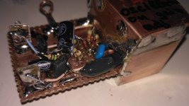
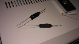
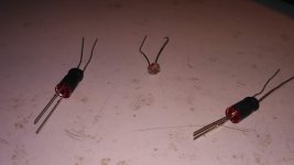
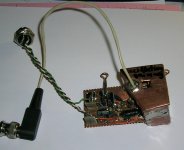
In my build I tried to make my own optocouplers as described by Rod Elliott (Project 145), using some photoresistors and LEDs from my junkbox with really good results. So, I enclosed the two components of the diy opto facing each other inside a piece of heatshrink tubing and encapsulated the whole thing in epoxy.I finally constructed two boards , one for me and one for a friend.
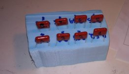
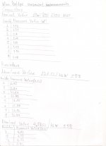
As far as the Wien bridge network components are concerned, I matched them using my multimeter.I wanted the frequency to be about 1KHz calling for 10 nF(nominal) capacitors and 16.7KΩ (12K in series with 4K7 ) resistors.
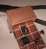
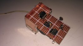
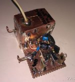
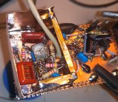
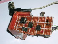
I provide an image with the final values used on each board. The Wien bridge opamp on bard 1 is a TL072 while on board 2 is an LF353P. Also instead of the 741 op amps I used two LM358 ones on each board.Finally I enclosed the oscillator side of the board in copper for shielding.
Adjustment:
The adjustment of the oscillator is pretty straightforward.Adjust the trimpot until a stable output waveform without clipping is achieved (in the two boards it measured around 0.8 to 1 Vrms regardless of supply voltage). If the trimpot is misadjusted , the output amplitude will either be zero or it will reach the opamp output voltage swing limits and clipping will start.
It should be noted that the output voltage can be fine tuned using this trim pot over a range of 80 mVrms. However by increasing Vout , jitter is reduced while THD is increased.
Construction:
This design calls for the use of an optocoupler as the main AGC element.
In my build I tried to make my own optocouplers as described by Rod Elliott (Project 145), using some photoresistors and LEDs from my junkbox with really good results. So, I enclosed the two components of the diy opto facing each other inside a piece of heatshrink tubing and encapsulated the whole thing in epoxy.I finally constructed two boards , one for me and one for a friend.
As far as the Wien bridge network components are concerned, I matched them using my multimeter.I wanted the frequency to be about 1KHz calling for 10 nF(nominal) capacitors and 16.7KΩ (12K in series with 4K7 ) resistors.
I provide an image with the final values used on each board. The Wien bridge opamp on bard 1 is a TL072 while on board 2 is an LF353P. Also instead of the 741 op amps I used two LM358 ones on each board.Finally I enclosed the oscillator side of the board in copper for shielding.
Adjustment:
The adjustment of the oscillator is pretty straightforward.Adjust the trimpot until a stable output waveform without clipping is achieved (in the two boards it measured around 0.8 to 1 Vrms regardless of supply voltage). If the trimpot is misadjusted , the output amplitude will either be zero or it will reach the opamp output voltage swing limits and clipping will start.
It should be noted that the output voltage can be fine tuned using this trim pot over a range of 80 mVrms. However by increasing Vout , jitter is reduced while THD is increased.
Attachments
-
 ldo schem.jpg169.7 KB · Views: 569
 -
 opto closeup.jpg781.5 KB · Views: 193
 -
 Back side oscillator shield.jpg638.8 KB · Views: 124
 -
 Board back side.jpg790.2 KB · Views: 130
 -
 complete board.jpg758 KB · Views: 157
 -
 Oscillator section.jpg838.8 KB · Views: 169
 -
 Capacitor measurements.jpg491.3 KB · Views: 411
 -
 opto components 2.jpg573.5 KB · Views: 417
 -
 opto components 1.jpg542 KB · Views: 452
 -
 component measurements.jpg182.3 KB · Views: 558
Last edited:
Measurements:
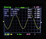
Supply is +/- 5Vdc. My board (board 2) outputs 830mVrms/ 976.4Hz on a output load of 10KΩ.
The output DC offset is 9.7mVdc.
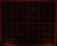
I provide photos of the output waveform from my Tek 475 and from a handheld JYE Tech 150 DSO.
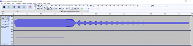
I also made 2 recordings (96KHz 24bit) with my soundcard, one of the oscillator settling (with a 10.5dB attenuator on the soundcard input) and one of it’s stable output (no attenuation). From the settling recording you can see that settling time is about 5s.
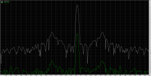
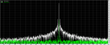
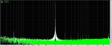
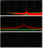
Finally I provide the results of the FFT analysis (FFT size: 2097152samples (resolution:92mHz) FFT Window: Kaiser20) of the stable output on RMAA.
From that follows, 0.0015%THD, 0.012%THD+N, 78.4dB S/N.
Also Jitter is +/-5Hz with sidebands 55dB below fundamental
Supply is +/- 5Vdc. My board (board 2) outputs 830mVrms/ 976.4Hz on a output load of 10KΩ.
The output DC offset is 9.7mVdc.
I provide photos of the output waveform from my Tek 475 and from a handheld JYE Tech 150 DSO.
I also made 2 recordings (96KHz 24bit) with my soundcard, one of the oscillator settling (with a 10.5dB attenuator on the soundcard input) and one of it’s stable output (no attenuation). From the settling recording you can see that settling time is about 5s.
Finally I provide the results of the FFT analysis (FFT size: 2097152samples (resolution:92mHz) FFT Window: Kaiser20) of the stable output on RMAA.
From that follows, 0.0015%THD, 0.012%THD+N, 78.4dB S/N.
Also Jitter is +/-5Hz with sidebands 55dB below fundamental
Attachments
-
 JLH ldo settling.png45.4 KB · Views: 98
 -
 JLH ldo stable out FFT fundamental(2).png48.5 KB · Views: 115
 -
 JLH ldo stable out FFT fundamental.png40.5 KB · Views: 136
 -
 JLH ldo stable out FFT(FFTsize 2097152 92mHz res Kaiser 20.png22 KB · Views: 162
 -
 JLH ldo stable out dso.jpg561.4 KB · Views: 137
 -
 JLH ldo stable out TEK475.jpg329.3 KB · Views: 124
Isn't it a little bit strange to make low distortion oscillator with high distortion opamps? Or it was a goal?
There are many much better ones, then tl071 and lf353, for example, a popular and quite cheap LM4562 and all that briliant family (lm49860, lm49720 ets).
I am shure that this oscillator can give much better results, with good enough opamps and sound card. As I can see - those results are similar to the soundcard results.
Last edited:
I finally constructed two boards , one for me and one for a friend.
That second oscillator board is here with me. Thank you Marios.
FFT length has to be 262144 samples and longer for sidebands to become visible
What you see is with an FFT size of 2097152 samples and Kaizer window (beta 20). 10sec recording of oscillator's output (sampling rate 96kHz, 32bit float)
Jitter (freq stability) is +/- 3Hz and 60dB below fundamental.
Exceptional results IMO.
E-Mu 0404 soundcard (1MOhm input)
Rec SW: WaveSpectra Ver.1.51E
FFT SW: RMAA Ver 6.45
It is very encouraging to see young boys departing from the mobile phone imprisonment trend, delving into old electronics magazines and burning their fingers with the soldering iron.

George
Attachments
Vovk Z,you are right about the opamps.However the goal of this project was to try and achieve good results with what I had in hand at that time and what was used originally by JLH.Also, I have put the oscillator opamp in a socket ,so, at any time in the future,I can replace it with something better.sn't it a little bit strange to make low distortion oscillator with high distortion opamps? Or it was a goal?
Marios
Vovk Z,you are right about the opamps.However the goal of this project was to try and achieve good results with what I had in hand at that time and what was used originally by JLH.Also, I have put the oscillator opamp in a socket ,so, at any time in the future,I can replace it with something better.
Marios
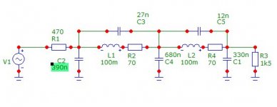
That signal generator is quite good already and as according to the article, the current through the LDR is a major cause of distortion, not much can be gained by changing opamps. What might give an improvement no opamp could provide is a simple passive filter. Already at 2 KHz it would provide 40 dB attenuation of the 2nd harmonic (and noise) and more than 80 dB at the 3rd.
Attachments
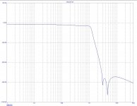
Thank you Aridace for reminding me of that parameter (It has been some time since I read this article).That signal generator is quite good already and as according to the article, the current through the LDR is a major cause of distortion, not much can be gained by changing opamps.
In the future, I may try such a filter at the oscillator output and post the results.
Marios
Thank you Aridace for reminding me of that parameter (It has been some time since I read this article).
In the future, I may try such a filter at the oscillator output and post the results.
Marios
My pleasure Marios. I must have overlooked the article at work so this time I read carefully. I'll start working with such low pass filters as well because the project for which the 100 mH coils were meant, no longer exists.
Jan
I understand. I am impressed of such a good enough results with such a bad opamps. Will take it (this schematics) into consideration.Vovk Z,you are right about the opamps.However the goal of this project was to try and achieve good results with what I had in hand at that time and what was used originally by JLH.Also, I have put the oscillator opamp in a socket ,so, at any time in the future,I can replace it with something better.

Last edited:
Thank you Jan for the passive filter schematic.What might give an improvement no opamp could provide is a simple passive filter.
I would like to ask you to provide some info on the coils.
Cored or air core? Dimensions? Are they off the self, or self made?
George
Thank you Jan for the passive filter schematic.
I would like to ask you to provide some info on the coils.
Cored or air core? Dimensions? Are they off the self, or self made?
George
The coils I have used and still am using are off the shelf, Toko 10RB series. The attached file shows specs and dimensions. I don't have an idea regarding availability though. But in case of unavailability, what matters for these coils is good Q, very low distortion and magnetic shielding. Any company in the business of producing line input and output transformers would be able to produce these 100 mH coils. BTW the coils generally are better than the specs indicate. The 70 ohm resistors are measured whereas according to the specs the value is 82 ohm.
Attachments
Two simple steps to improving before building a low pass filter- first get lower distortion LDR's (Silonex or whatever their current name is) and second minimize the level across them. Selling time increases with lower level on the LDR.
Sound Technology addressed this with a two stage AGC, using a FET for fast selling and switching to an LDR for low distortion, see attached circuit. This with good opamps can have a distortion below .0006% pretty easily but its not simple. Adding a resistor from the drain to the gate of the Jfet can reduce the distortion of that mode a lot as well.
Sound Technology addressed this with a two stage AGC, using a FET for fast selling and switching to an LDR for low distortion, see attached circuit. This with good opamps can have a distortion below .0006% pretty easily but its not simple. Adding a resistor from the drain to the gate of the Jfet can reduce the distortion of that mode a lot as well.
Attachments
Thank you for the schematic, Demian.
As you indicate, the FET handles the fast settling and the LDR handles the slower, larger adjustments. I believe the U3 integrator adjusts the LDR so that Q1 gate voltage is driven to a nominal -0.767V. That must be its "sweet spot" for best distortion. Thus, the LDR handles the larger adjustments needed to accommodate component tolerances associated with frequency switching and leaves the FET adjusted for lowest distortion. Very clever!
As you mentioned, the only trick not adopted was the drain-gate feedback linearization.
Thanks again.
The ST generators are notorious for that circuit being "off and constantly switching.
Done right drain gate feedback can get the harmonics in the -140 dB range, across a narrow range of frequencies. The best current designs use an analog multiplier because its more straightforward. There is lots of discussion in the long oscillator thread: Low-distortion Audio-range Oscillator
Given that I value my time just above zero I buy Victor's oscillators. I can't compete even if the parts were free. His are at the state of the art and affordable. Low-distortion Audio-range Oscillator
Last edited:
Thanks Jan.
George
You're welcome George.
1audio , thank you for the advice. Is there a way of reducing the level across the LDR on JLH's design?Two simple steps to improving before building a low pass filter- first get lower distortion LDR's (Silonex or whatever their current name is) and second minimize the level across them.
Several steps. First lowest distortion opamps are essential. LME4971-LME49720 are a great fit for this. There are others to look at as well. Second, there is a tradeoff between settling time and distortion. Finally a single frequency oscillator is a easier to optimize that a tuneable oscillator.
That said, the resistor in series with the optocoupler R6 and parallel resistor R5 control the level as well as the overall operating level. Operate at a lower level if you can. Increase R6 until the opto doesn't stabilize. Reduce R5 for the same goal. Back off both. You will find that it takes a long time to stabilize but the distortion will be lower. the opto generates odd harmonics so you may be able to better optimize by checking those as you adjust. The AGC will most likely generate even harmonics.
That said, the resistor in series with the optocoupler R6 and parallel resistor R5 control the level as well as the overall operating level. Operate at a lower level if you can. Increase R6 until the opto doesn't stabilize. Reduce R5 for the same goal. Back off both. You will find that it takes a long time to stabilize but the distortion will be lower. the opto generates odd harmonics so you may be able to better optimize by checking those as you adjust. The AGC will most likely generate even harmonics.
I believe 1audio offered great advice on opamp choice and especially exploring interaction between LDR amplitude/component values/settling time/distortion. I have one addition observation re LDR amplitude.
You may have noticed earlier that the gain of the of the frequency determining network from U1B to U1A output is only 0.5 (and consequently the gain of the U1B stage has to be 2.0 for stable oscillation). If you impedance scale R1 and C1 to 8.35K and 0.2uF, the gain of the U1A stage will double to 1.0 You can then double the value of VR1, reducing U1B gain to 1.0. The amplitude across the LDR will drop in half. You may be able to extend this rationale still further.
A few other comments about this circuit, which is probably an experimenter’s delight.")
+/- 5 Volts may be a bit low for supply rails; performance might benefit from higher supply voltage.
A resistor between U1B and the output connector might be advisable to prevent opamp oscillation when driving long cables with high capacitance.
I’d recommend a current limiting resistor in series with the opto-coupler’s LED, chosen appropriately for rated LED current in concert with the chosen supply voltage.
Finally, the Level Control loop: I suspect the lack of a current limiting resistor driving the LDR LED causes inordinate sensitivity to the setting of VR1; without an appropriate resistor, LED current rises precipitously with increasing U3A voltage. This leads, I believe, to rapid increases in control loop gain and subsequent control loop oscillation; I speculate this is what prevents the output from being driven to higher output levels without unacceptable misbehavior.
IMO, the original manner in which 68K (R13) is connected to U3A will frustrate experimentation with LDR amplitude--- varying either VR1 adjustment or R6 or will simultaneously change output amplitude, making it tedious at best to attribute changed performance to LDR amplitude. More conventional and more convenient is to configure U3A as an integrator so that output amplitude is held constant irrespective of adjustment of VR1, R6, etc. To implement this revision, I suggest a potentiometer (any value between 10K and 100k) connected between ground and the B-minus rail. Connect R13 to the pot’s wiper instead of the U3 output. This will make it easy to vary output level in concert with other experiments, or to return the wiper at a consistent DC voltage for repeatability.
Good luck. Cheers!
You may have noticed earlier that the gain of the of the frequency determining network from U1B to U1A output is only 0.5 (and consequently the gain of the U1B stage has to be 2.0 for stable oscillation). If you impedance scale R1 and C1 to 8.35K and 0.2uF, the gain of the U1A stage will double to 1.0 You can then double the value of VR1, reducing U1B gain to 1.0. The amplitude across the LDR will drop in half. You may be able to extend this rationale still further.
A few other comments about this circuit, which is probably an experimenter’s delight.
+/- 5 Volts may be a bit low for supply rails; performance might benefit from higher supply voltage.
A resistor between U1B and the output connector might be advisable to prevent opamp oscillation when driving long cables with high capacitance.
I’d recommend a current limiting resistor in series with the opto-coupler’s LED, chosen appropriately for rated LED current in concert with the chosen supply voltage.
Finally, the Level Control loop: I suspect the lack of a current limiting resistor driving the LDR LED causes inordinate sensitivity to the setting of VR1; without an appropriate resistor, LED current rises precipitously with increasing U3A voltage. This leads, I believe, to rapid increases in control loop gain and subsequent control loop oscillation; I speculate this is what prevents the output from being driven to higher output levels without unacceptable misbehavior.
IMO, the original manner in which 68K (R13) is connected to U3A will frustrate experimentation with LDR amplitude--- varying either VR1 adjustment or R6 or will simultaneously change output amplitude, making it tedious at best to attribute changed performance to LDR amplitude. More conventional and more convenient is to configure U3A as an integrator so that output amplitude is held constant irrespective of adjustment of VR1, R6, etc. To implement this revision, I suggest a potentiometer (any value between 10K and 100k) connected between ground and the B-minus rail. Connect R13 to the pot’s wiper instead of the U3 output. This will make it easy to vary output level in concert with other experiments, or to return the wiper at a consistent DC voltage for repeatability.
Good luck. Cheers!
1audio , BSST , I really appreciate your suggestions.Unfortunately, most of the changes will have to wait untill I find some more free time and stop being bored of removing the oscillator shield. However I may buy lower distortion opamps and try them out. Also, what value of resistor shall I put in series with the output? Around 47Ω is OK?
Marios
Marios
- Status
- This old topic is closed. If you want to reopen this topic, contact a moderator using the "Report Post" button.
- Home
- Design & Build
- Equipment & Tools
- John Linsley Hood's low distortion oscillator