Hi,
I recently got a Tek 2445 in DOA condition. Sine it is a nice analog scope with some digital features I would like to revive it. Turns out the power supply had a blown main rectifier. Now I get the scope to power up. On initial power up it greeted me with an Error. (only once, since no error message came up again)
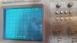
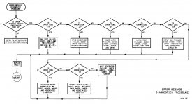
GP TEST 11 FAIL 06
Needless to say, this error is not listed in the service manual for the Tektronix 2445, nor any information about the GPIB Option. The weird part, altho the board is labeled with GPIB option, there is no GPIB connector on this scope. Unfortunately the back plastic cover and the fan wheel are missing, so I have no information on the serial number or possible installed options.
Playing with the control knobs, I get something on the screen, but does not look good for the moment. Eventually I noticed the controls for all Trace position and Trace separation do not work.
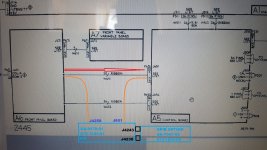
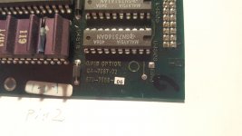
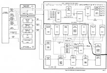
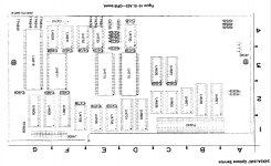
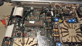
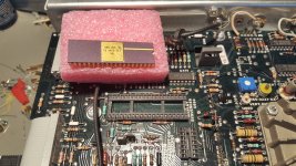
I find in the service manual that these potentiometer controls connect directly from the Front Panel Board A6 to the Control Board A5 by ribbon W651. When measuring, I do get no such signals to the control board. Turns out the signals are routed through undocumented A20 J4258 and A20 J651. From there I traced the connection to A20 J4238 connector which connects to the GPIB Option board. This is getting weird now as I have no idea what a GPIB option board possibly has to do with the trace positions
Can someone help and give a few pointer or has documentation on the A20 board and on the GPIB Options board ? Or an idea what this is all about.
For now I will just jumper these signals to connect directly to the A5 board and continue troubleshooting this scope.
================== Update 1 ===================
Well, well, well, I managed to find the 24x5/2467 Options Service Menu, sure enough the mystery board A20 and the GPIB option board is mentioned there along with other useful detailed information such as diagrams. This largely matches what I found out anyway.
The SM suggest that certain EPROM are coded to support the A20 Buffer Board and Options installed on it. There are also suppose to be jumpers set as well. Altho the SM describes there should be a self test GP xx in the menu, it is not, only the scope standard tests are there.
Well, I could not find any specific jumpers to the set for the GPIB option, so since there is no GP self test in the menu I decided to see what happens if I just completely disconnect the A20 board. Funny the scope does not complain at all and passes all self tests.
I recently got a Tek 2445 in DOA condition. Sine it is a nice analog scope with some digital features I would like to revive it. Turns out the power supply had a blown main rectifier. Now I get the scope to power up. On initial power up it greeted me with an Error. (only once, since no error message came up again)
GP TEST 11 FAIL 06
Needless to say, this error is not listed in the service manual for the Tektronix 2445, nor any information about the GPIB Option. The weird part, altho the board is labeled with GPIB option, there is no GPIB connector on this scope. Unfortunately the back plastic cover and the fan wheel are missing, so I have no information on the serial number or possible installed options.
Playing with the control knobs, I get something on the screen, but does not look good for the moment. Eventually I noticed the controls for all Trace position and Trace separation do not work.
I find in the service manual that these potentiometer controls connect directly from the Front Panel Board A6 to the Control Board A5 by ribbon W651. When measuring, I do get no such signals to the control board. Turns out the signals are routed through undocumented A20 J4258 and A20 J651. From there I traced the connection to A20 J4238 connector which connects to the GPIB Option board. This is getting weird now as I have no idea what a GPIB option board possibly has to do with the trace positions
Can someone help and give a few pointer or has documentation on the A20 board and on the GPIB Options board ? Or an idea what this is all about.
For now I will just jumper these signals to connect directly to the A5 board and continue troubleshooting this scope.
================== Update 1 ===================
Well, well, well, I managed to find the 24x5/2467 Options Service Menu, sure enough the mystery board A20 and the GPIB option board is mentioned there along with other useful detailed information such as diagrams. This largely matches what I found out anyway.
The SM suggest that certain EPROM are coded to support the A20 Buffer Board and Options installed on it. There are also suppose to be jumpers set as well. Altho the SM describes there should be a self test GP xx in the menu, it is not, only the scope standard tests are there.
Well, I could not find any specific jumpers to the set for the GPIB option, so since there is no GP self test in the menu I decided to see what happens if I just completely disconnect the A20 board. Funny the scope does not complain at all and passes all self tests.
Attachments
-
 _20190404_113439.jpg724.4 KB · Views: 611
 -
 _20190405_131835.jpg279.1 KB · Views: 415
 -
 _20190405_131715_001.jpg420.7 KB · Views: 395
 -
 _20190405_131535.jpg723.7 KB · Views: 424
 -
 _20190405_122013.jpg589.7 KB · Views: 493
 -
 _20190405_120316.jpg787.6 KB · Views: 528
 -
 _20190404_125213.jpg564.6 KB · Views: 682
 -
 _20190404_115455.jpg541.6 KB · Views: 661
Last edited:
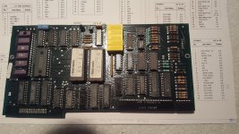
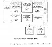
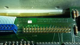
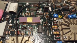
Hmmmm, slight difference between the GPIB board I have and what is documented.
Seems the connector P4238 and the parts for the analog mumbo jumbo on the trace positions has disappeared. Lovely.
Seems the connector P4238 and the parts for the analog mumbo jumbo on the trace positions has disappeared. Lovely.
Attachments

Last edited:
=================== Update 2 ====================
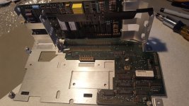
As I don't need nor care for the GPIB option I will just permanently remove the boards, but what is nagging me is the trigger / sweep issue.
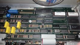
For trial, I swapped the A-Sweep chip with the B-Sweep chip, makes no difference. I tried to aggravate the issue with cold spray on the Sequencer Chip U650 and on the CPU and EPROM chips on the controller board, again makes no difference. At this point I am running out of ideas where to look, for the moment I suspect the Sequencer to be flaky. I ordered a new chip but has not yet arrived. From what I can measure the signals seem all exactly as documented as long as I have the timebase setting at 50us or faster.
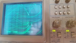
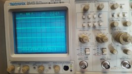
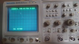
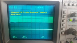
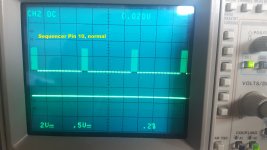
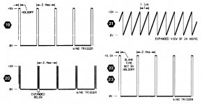
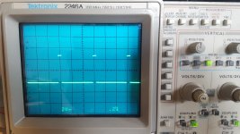
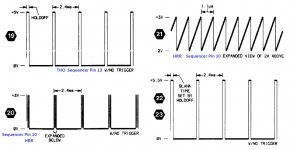
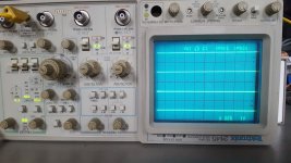
Eventually Pin10 (HRR) on the Sequencer caught my attention, when everything is normal there are bursts of saw-tooth every few milliseconds, as shown signal waveform [20] and [21] in the service documentation. However, when I have the timebase setting set to slower than 50us I measure no bursts anymore, but a continuous stream of saw-tooth pulses at this pin. (see below attached)
I found documentation for all these lovely Tektronix custom chips including some documentation on the sequencer chip, Pin 10 is defined as: Hold Off Oscillator Input with External 150pF Capacitor (Internal Active Pull down)
It says, at the end of sweep, trigger hold-off (THO) is initiated by the Sequencer. At the same time, an on-chip oscillator is started. After a programmed number of oscillations, THO ends.
Furthermore the documentation says, the Sequencer gets data from the CPU serially shifted into it, the data is 55 bits long and determines the functionality of the Sequencer. Transitions of the control clock shifts data in, clears the divider chain, and initiates a signal 'Control Hold-Off' that blanks the CRT and prevents triggering for at least Tclock x 10^3 after the last control clock goes high.
As I understand it, Sequencer Pin 25 (CD) Control Data and Pin 24 (CC) Control clock are controlled by the CPU and data is send to all chips on this serial bus. Since other functions of the scope seem not impacted I assume for now the data bus and CPU data bits are fine. When I look at these two pins I see proper level signal and a bit stream occurring every time a the timebase knob is operated.
I just don't know how exactly the bits are to be coded and this bit stream is suppose to look like.
For the fun of it, I also replaced Q155 (which directly connects to Pin 10), again makes no difference.
I also verified the signal coming in on U165C Pin 9, DC between +/- 0.7V depending on the Hold-Off knob setting. U165 has proper power supply of +/- 5V also, verified.
================== Update 3 =====================
Screenshots of Sequencer Pin 10, with problem Timebase setting and without (see below)
As I don't need nor care for the GPIB option I will just permanently remove the boards, but what is nagging me is the trigger / sweep issue.
For trial, I swapped the A-Sweep chip with the B-Sweep chip, makes no difference. I tried to aggravate the issue with cold spray on the Sequencer Chip U650 and on the CPU and EPROM chips on the controller board, again makes no difference. At this point I am running out of ideas where to look, for the moment I suspect the Sequencer to be flaky. I ordered a new chip but has not yet arrived. From what I can measure the signals seem all exactly as documented as long as I have the timebase setting at 50us or faster.
Eventually Pin10 (HRR) on the Sequencer caught my attention, when everything is normal there are bursts of saw-tooth every few milliseconds, as shown signal waveform [20] and [21] in the service documentation. However, when I have the timebase setting set to slower than 50us I measure no bursts anymore, but a continuous stream of saw-tooth pulses at this pin. (see below attached)
I found documentation for all these lovely Tektronix custom chips including some documentation on the sequencer chip, Pin 10 is defined as: Hold Off Oscillator Input with External 150pF Capacitor (Internal Active Pull down)
It says, at the end of sweep, trigger hold-off (THO) is initiated by the Sequencer. At the same time, an on-chip oscillator is started. After a programmed number of oscillations, THO ends.
Furthermore the documentation says, the Sequencer gets data from the CPU serially shifted into it, the data is 55 bits long and determines the functionality of the Sequencer. Transitions of the control clock shifts data in, clears the divider chain, and initiates a signal 'Control Hold-Off' that blanks the CRT and prevents triggering for at least Tclock x 10^3 after the last control clock goes high.
As I understand it, Sequencer Pin 25 (CD) Control Data and Pin 24 (CC) Control clock are controlled by the CPU and data is send to all chips on this serial bus. Since other functions of the scope seem not impacted I assume for now the data bus and CPU data bits are fine. When I look at these two pins I see proper level signal and a bit stream occurring every time a the timebase knob is operated.
I just don't know how exactly the bits are to be coded and this bit stream is suppose to look like.
For the fun of it, I also replaced Q155 (which directly connects to Pin 10), again makes no difference.
I also verified the signal coming in on U165C Pin 9, DC between +/- 0.7V depending on the Hold-Off knob setting. U165 has proper power supply of +/- 5V also, verified.
================== Update 3 =====================
Screenshots of Sequencer Pin 10, with problem Timebase setting and without (see below)
Attachments
Hi Jan,
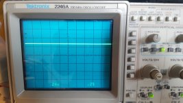
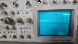
Thanks for offering some help, yes, when the scope seem to operate normal, I measure pulse bursts as described matching waveform 19 (Pin13 THO), 20 and 21 (Pin10 HRR).
When the scope exhibits the problem, there are no more pulses observed on 19, 20 and 21. All I get is 19 stuck at high and 20 / 21 a ever ending saw-tooth waveform as if the scope is stuck in permanent Hold-Off. No traces are shown on the CRT, only readouts.
Pin 13 THO (waveform 19), When operating normal
Attachments

Last edited:
============== Update 5 ==============
Final Update:
Managed to get a replacement synchronizer Chip, plugged into the socket - problem gone.
Final Update:
Managed to get a replacement synchronizer Chip, plugged into the socket - problem gone.
Attachments
- Status
- This old topic is closed. If you want to reopen this topic, contact a moderator using the "Report Post" button.
- Home
- Design & Build
- Equipment & Tools
- Tektronix 2445 repair, GPIB option undocumented