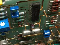
This recently acquired HP339A will not read below -4 db regardless of what signal source (internal or external) I feed it. On a positive note the internal oscillator is working fine as proven by hooking it to my HP334A. I have performed an internal inspection (it is very clean) and can see no internal damage and all wafer switches look good and the two glass onboard fuses check good.
I first discovered this problem while performing the Operational Verification Checks listed in the manual, it passes all tests up to section 3-52 step H which it fails. I also noticed another thing. It is my understanding that when using an external signal source both frequency led's should be extinguished when those controls are adjusted within range of the input frequency.
On this unit the left hand led never goes off, it does change brightness but never fully extinguishes. Also, when connected to the internal oscillator both led's stay on, is this normal? Could there be an issue with the null circuit?
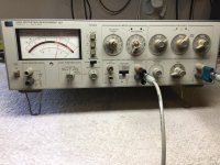

Yes sir, I have a Tektronix 2247A scope and a HP3312A signal source, though it is not a very low distortion unit at 0.5% thd. I also have a signal source available from a Kikusui KSG4310 that provides an ultra low distortion signal source starting at 10 khz.
I truly appreciate any help you can provide to trouble shoot this problem. Thank you!
I'm in the Western zone of the US, California.
I truly appreciate any help you can provide to trouble shoot this problem. Thank you!
I'm in the Western zone of the US, California.
Time zone difference isn’t too bad. From your user-name, I feared you might be in Aussie land. ;-)
It does sound like auto-null problems, frequency arrows acting weird, so we can focus there. But a few preliminary, scatter-shot questions:
-4dB sure isn’t much null depth. Is there any hint of a notch response as you vary applied external generator frequency?
Is the monitor output a clean sine wave?
On board A3, do TP1, TP3, TP4 and AUTO SET test points present clean sine waves with bias near 0 volts, DC? (Make sure you’re using a X10 scope probe to ensure modest capacitive loading of the opamps; X1 probes can provoke opamp oscillation.)
On board A4, are there clean sine waves on TP3, 4, 5?
Zeroing in on odd arrow behavior, would you describe waveforms /voltages on TP1 and TP2? In a properly functioning analyzer, these voltages should be DC signals between 0 and about 9V. If optocoupler drivers are working properly, voltage at R55 should track TP2 within a few millivolts; similarly, voltage at R23 should track TP1 within mVs.
Do output voltages on U6 opamp sections make sense in view of the voltage observed on TP2? I doubt the health of U6 is the underlying problem, but insight to why one arrow led is “stuck” and the other acting oddly might be insightful. Let me know if you need more detail than I’m providing.
I hope these tests will point us in the right direction.
Good luck!
I'll tackle a few steps at a time and update as I go.
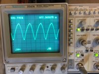
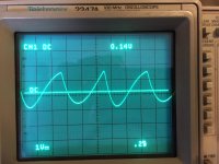
Yes there is some notch response as I vary the applied external generator frequency. With the 339A frequency controls set at 1khz (Oscillator Level control switched to off) and the external source feeding 1khz I get about -4db. When I dial down the external frequency to about 877 hz I get my lowest dip on the 339a at -13db however as the picture shows the signal at the 339A monitor out looks a little ordinary. If I adjust back to an external 1khz input the sinewave goes back to looking good. I will shortly proceed with the next steps you mentioned.
Oh, my user name...expat for over 30 years but born and raised in Melbourne Australia.
On board A3, do TP1, TP3, TP4 and AUTO SET test points present clean sine waves with bias near 0 volts, DC?
Yes but I do not know what or where to find the AUTO SET test points?
On board A4, are there clean sine waves on TP3, 4, 5?
Yes
Yes there is some notch response as I vary the applied external generator frequency. With the 339A frequency controls set at 1khz (Oscillator Level control switched to off) and the external source feeding 1khz I get about -4db. When I dial down the external frequency to about 877 hz I get my lowest dip on the 339a at -13db however as the picture shows the signal at the 339A monitor out looks a little ordinary. If I adjust back to an external 1khz input the sinewave goes back to looking good. I will shortly proceed with the next steps you mentioned.
Oh, my user name...expat for over 30 years but born and raised in Melbourne Australia.

On board A3, do TP1, TP3, TP4 and AUTO SET test points present clean sine waves with bias near 0 volts, DC?
Yes but I do not know what or where to find the AUTO SET test points?
On board A4, are there clean sine waves on TP3, 4, 5?
Yes
Ok, we've arrived at a trouble spot!
You mentioned earlier finding a weak null with the oscillator tuned to 877 Hz with analyzer set to 1KHz. Would you return to that arrangement and monitor A4- TP1 and TP2 as you tweak oscillator frequency and amplitude. The idea is to get TP1 and 2 to show some non-zero activity. Also watch the arrow LEDs for any associated activity.
You mentioned earlier finding a weak null with the oscillator tuned to 877 Hz with analyzer set to 1KHz. Would you return to that arrangement and monitor A4- TP1 and TP2 as you tweak oscillator frequency and amplitude. The idea is to get TP1 and 2 to show some non-zero activity. Also watch the arrow LEDs for any associated activity.
If optocoupler drivers are working properly, voltage at R55 should track TP2 within a few millivolts; similarly, voltage at R23 should track TP1 within mVs.
R55 is tracking TP2
R23 is NOT tracking TP1 (TP1 = -61mV, R23 = -1mV
You mentioned earlier finding a weak null with the oscillator tuned to 877 Hz with analyzer set to 1KHz. Would you return to that arrangement and monitor A4- TP1 and TP2 as you tweak oscillator frequency and amplitude. The idea is to get TP1 and 2 to show some non-zero activity. Also watch the arrow LEDs for any associated activity.
TP1 is now at 0.8V dc
TP2 is now at virtually 0V
Input frequency at 877 Hz, amplitude at 1V rms
Left led on, right led off
Adjusting amplitude has no affect on output voltages at TP1 or TP2. It also has no affect on the Frequency led's (the left led is always on), however it does affect the Input Range led's with both alternating on and off as amplitude is increased and decreased but I would assume that to be normal behaviour?
I was being a bet reckless earlier when I described tracking. This tracking is true only when TP1 or 2 is positive, as the drivers (i.e. Q1 or Q2) can only source current, not sink. So the jury is still out re TP1.
I'm suspicious that the amplitude control loop is at fault. That's what motivates the experiment to tune for that weak null and see if phase loop shows any life.
You can compare U3A output with U5A output. They will have "chopped-up" waveforms but should average to 0V when the loops are working properly. You might spot an obvious problem.
Here's a way to exercise the optodrivers to confirm they're operable. The idea is to force some current into the integrator formed by U3B so that is forced to clamp by the 9V zener, CR5. Then you can confirm TP1 to R23 tracking. A 10K resistor tacked from -15V to U3 pin 6 should do the trick. You can do a similar test at U6B if there's any doubt.
I have to break for errands but will try to check back.
Good luck!
Let me back up the truck a moment on those TP1 and TP2 voltages and I will get back to you. I was using my scope but let me try with a Fluke 87V.
Makes a big difference when you forget to switch the scope probe back to X1
lol
Let me back track a few steps and present the truth this time!
Input frequency back to 1 khz at 1V rms
TP1 = -620mV
R23 = 0V
TP2 = +180mV
R55 tracking
Input frequency 877 hz at 1v rms
TP1 = +8.4v
R23 = 0v
TP2 = +180mV
R55 tracking
...and my apologies for the earlier mess up, I know how frustrating that can be!
...and as before, amplitude input changes do not change the voltages at TP1 or TP2
U3A output at 877 Hz
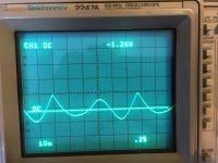
U5A output at 877 Hz
Makes a big difference when you forget to switch the scope probe back to X1
lol
Let me back track a few steps and present the truth this time!
Input frequency back to 1 khz at 1V rms
TP1 = -620mV
R23 = 0V
TP2 = +180mV
R55 tracking
Input frequency 877 hz at 1v rms
TP1 = +8.4v
R23 = 0v
TP2 = +180mV
R55 tracking
...and my apologies for the earlier mess up, I know how frustrating that can be!
...and as before, amplitude input changes do not change the voltages at TP1 or TP2
U3A output at 877 Hz

U5A output at 877 Hz

Input frequency 877 hz at 1v rms
TP1 = +8.4v
R23 = 0v
Something very wrong here. There may be more than one problem, but the above issue must be resolved. Would you report voltages at Q1 base and emitter. We know R23 voltage is 0, but try to trace continuity to the LED in the E1 coupler on the A3 board. Said another way, what voltages appear on the anode and cathode of the E1 LED?
Clever annotation! 
So if I surmise correctly, base and emitter voltage are 0V. U3 pin 10 is +8.4V, pin 9 is 0V. U3 pin 8 should be near the +15 rail. If it is, in fact, near +15V, then R24 must be open. If pin8 is 0V, then opamp appears to be failed.
Of course all this should be double checked.
Clarification. I'm noting possible fault voltages given that the circuit is not working.
I should have mentioned earlier, I am truly grateful for your knowledge and time and truly appreciate your help in this endeavor! Hopefully in the end I can place this fine piece of gear back on the work bench where it belongs. Have a good evening, and again thank you very much!
Do you know if I should stick to the original old stock National LM348N or is there a better new equivalent? Thanks
Do you know if I should stick to the original old stock National LM348N or is there a better new equivalent? Thanks
Your quite right about the specified opamp. I think I may be recalling a substitute made by another DIY.
Since I don't know of a "better" part, I guess I'd stick with the original. They're still available, cheap, and not critical in this portion of the instrument anyway. I'd advise buying a few spares, especially given peculiar behavior of frequency LEDs.
Getting the amplitude loop working will make other misbehavior easier to trouble shoot. I fear there's more than one defect in play.
In post #12, I should have inquired about continuity to the E2 opto-coupler, not E1. I still suspect the U3C failure, but double-checking is recommended before resorting to replacing the IC.
I’ve been trying to understand the strange behavior of the arrow LEDs.
To organize my thinking and make things less tedious, I generated a truth table to describe behavior of the opamps in response to phase control voltages. I’ve labeled the voltage at the + terminal of C26 as Vc26 in the table below. Also, if the resistor values on the HP schematic are correct, the annotated voltage at the R59, R60 node (both 200 ohm) should be 1.0V rather than the printed 0.7V. The table incorporates that assumption. If a comparison function is “True”, the associated diode-ORed LED should light.
The upshot: in a properly operating analyzer with the fundamental nulled, the TP2 voltage will lie between +8.5V and +1.0V, and both LEDs will be off. Vc26 will have 0V (and U5A pin 1 average) so that integrator input current is 0.
I’m going to engage in some wild guess work with scant data. You reported earlier that TP2 was near zero, so that would explain CCW arrow lit responding to U6C. During one experiment, you were able to get the CW arrow extinguished, but CCW remained on. I’m going to infer that by adjusting external generator frequency, you managed to clear the U6D comparison; TP2 should have integrated to a larger voltage, but didn’t. I suspect U5B failure or a nearby component, especially shorted C25.
- Status
- This old topic is closed. If you want to reopen this topic, contact a moderator using the "Report Post" button.
- Home
- Design & Build
- Equipment & Tools
- HP339A need help, distortion section not functioning correctly
