Hello,
First, Thank you for your interest about the project.
In general way, it is better to put the regulator that supply sensitives sections as near as possible of these.
So maybe you can take the +5V rail available on AAPSU01 and put the 3.3V LDO near the target IC/section.
You can of course also add this 3.3v regulator on the AAPSU01 design, before or after the 5V regulator.
I would prefer after, this will lower the losses on 3v3 reg and improve ripple rejection.
Anyway that really depend on your design itself, and if each 5V/3.3V power rails mix analog
and fast digital circuitry.
I hope that help.
Regards.
Frex
Hello,
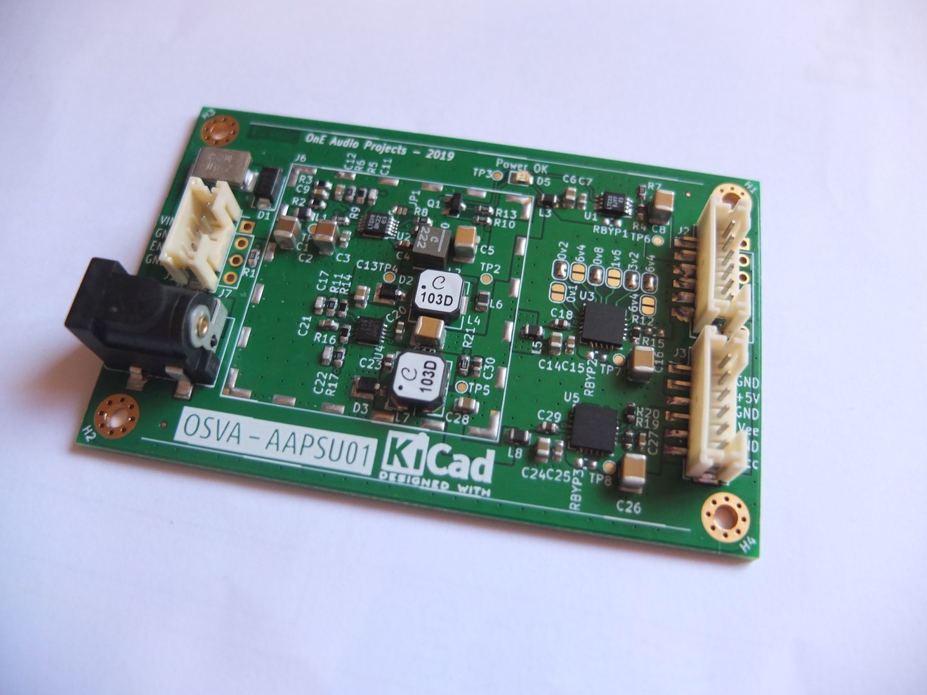
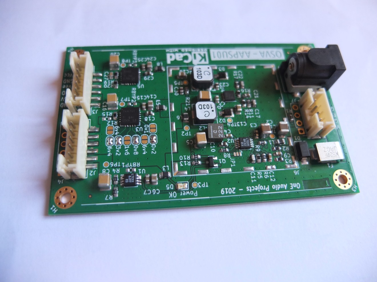
I finally soldered all parts of the AAPSU01 power supply board, for the first time using a stencil.
Despite the strong summer heat, all has been fine and each part well soldered ! Ouf !.
I made many tests on it and it work as expected, i can get all reached outputs currents without problem.
When i completed the measurements report, i will post results.
I don't have made serious output noise measurements yet, i will be the next step.
So, just for fun some picture of the prototype board below.
Regards.
Frex.
Hello,
First, Thank you for your interest about the project.
In general way, it is better to put the regulator that supply sensitives sections as near as possible of these.
So maybe you can take the +5V rail available on AAPSU01 and put the 3.3V LDO near the target IC/section.
You can of course also add this 3.3v regulator on the AAPSU01 design, before or after the 5V regulator.
I would prefer after, this will lower the losses on 3v3 reg and improve ripple rejection.
Anyway that really depend on your design itself, and if each 5V/3.3V power rails mix analog
and fast digital circuitry.
I hope that help.
Regards.
Frex
That makes sense. Thanks a lot for your help, very much appreciated!
AAPSU01v1 power supply PCB noise measurements and more...
Hello,
I made these days some tests on the AAPSU01v1 prototype board.
It include efficiency measurements on each outputs, and extended noise measurements.
The AAPSU01v1 has been test at full power (~ 15W) and work safely at this level.
(Note : +5V / 1.1A , +12V 500mA and -12V/250mA).
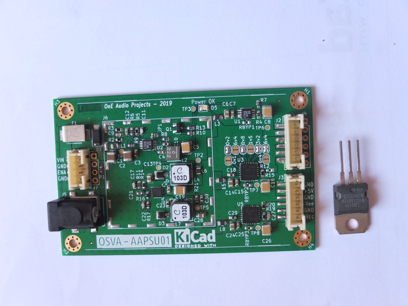
Because no thru-hole parts are required, if needed the PCB bottom side can be put
directly on aluminum panel to serve as heat-sink (with an thin insulted sheet to avoid short circuit!).
I measured overall efficiency for each outputs, for 12 and 20V DC input (all output loaded).
Results can be showed on graphs below :
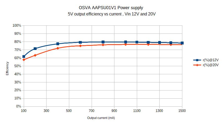
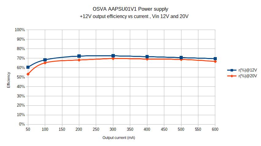
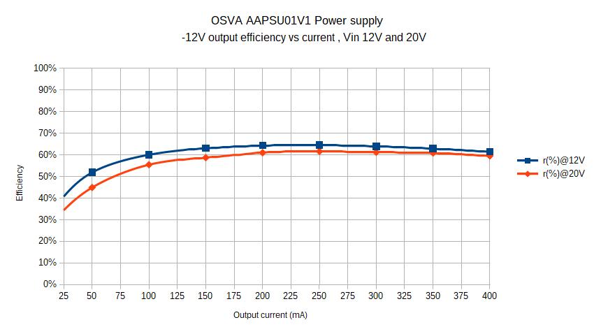
The efficiency is not very high, but far better than a full linear PSU and considering
the size of board (80x50 mm) for this output power (15W).
Now, it's time to for serious noise measurements.
To begin and for reference, I made first some noise measurements
on different power supplies and for various measurement bandwidth.
I tested power supply listed below :
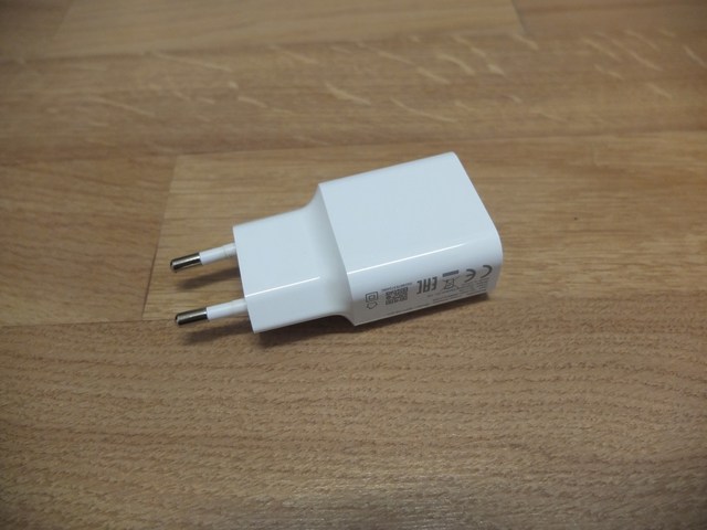
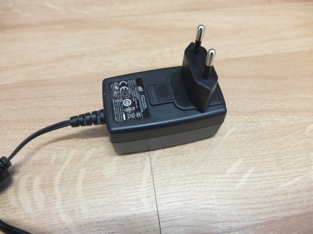
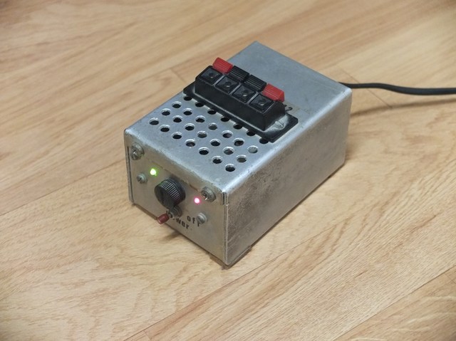
Below,some pictures of each DUT :
Xiaomi USB charger 5V and ENG 12V wall adapter
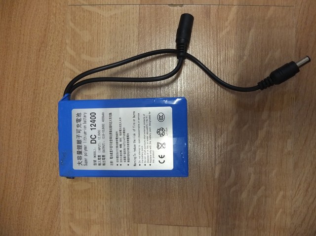
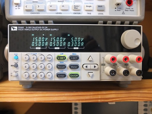
12V 12400 Li-ion battery pack and ITECH IT6302 lab power supply
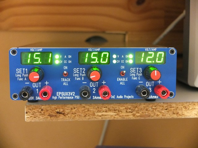
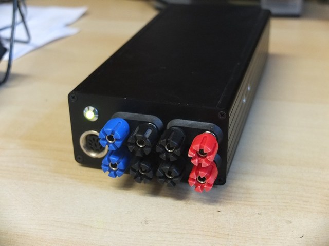
EPSUX3v2 DIY power supply and SSR01/SSR01 +/15V ultralow noise PSU
Old school 12V PSU (LM7812 based)
I made the noise measurements using two methods (bandwidth) :
1) 10Hz-100kHz standard noise bandwidth measurements
(using ERMSDCV2 design : + 80dB low noise amplifier with 10Hz-100kHz pass-band filter).
2) 5Hz-20MHz Wide-band noise measurements using RACAL-DANA 9300F millivoltmeter.
These two measurements schemes allow to show noise contribution in various bandwidth
and then give more consistent results.
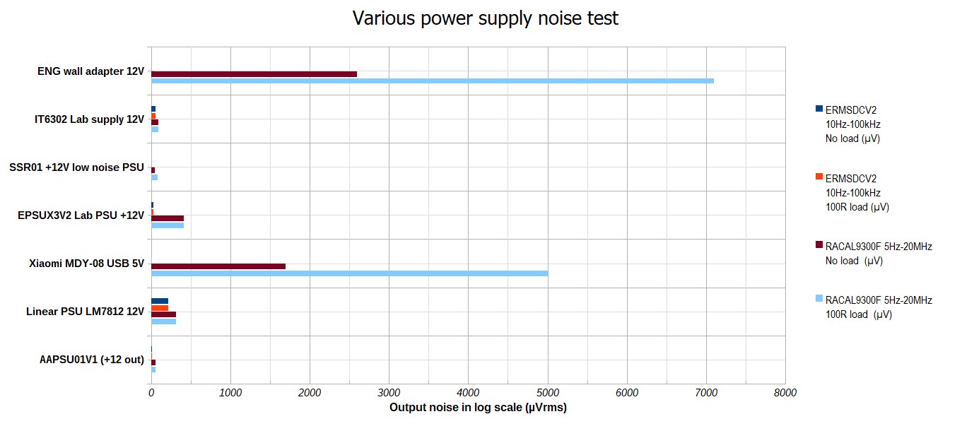
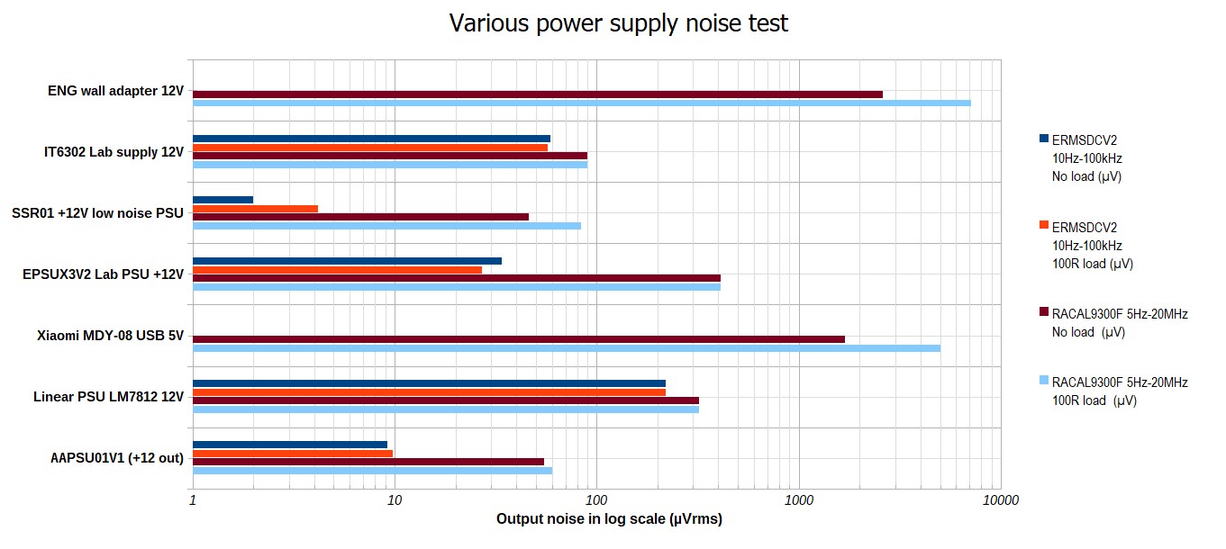
The graph below summarized the results (in linear and log scale of noise level):
Various power supply noise (linear scale) :
Various power supply noise (log scale) :
The picture below show noise spectrum for these various PSU :
(Note that there is only PSU with noise < 1mV to not overload the test setup of ERMSDCV2).
Various power supply noise spectrum in audio 10Hz - 100kHz bandwidth :
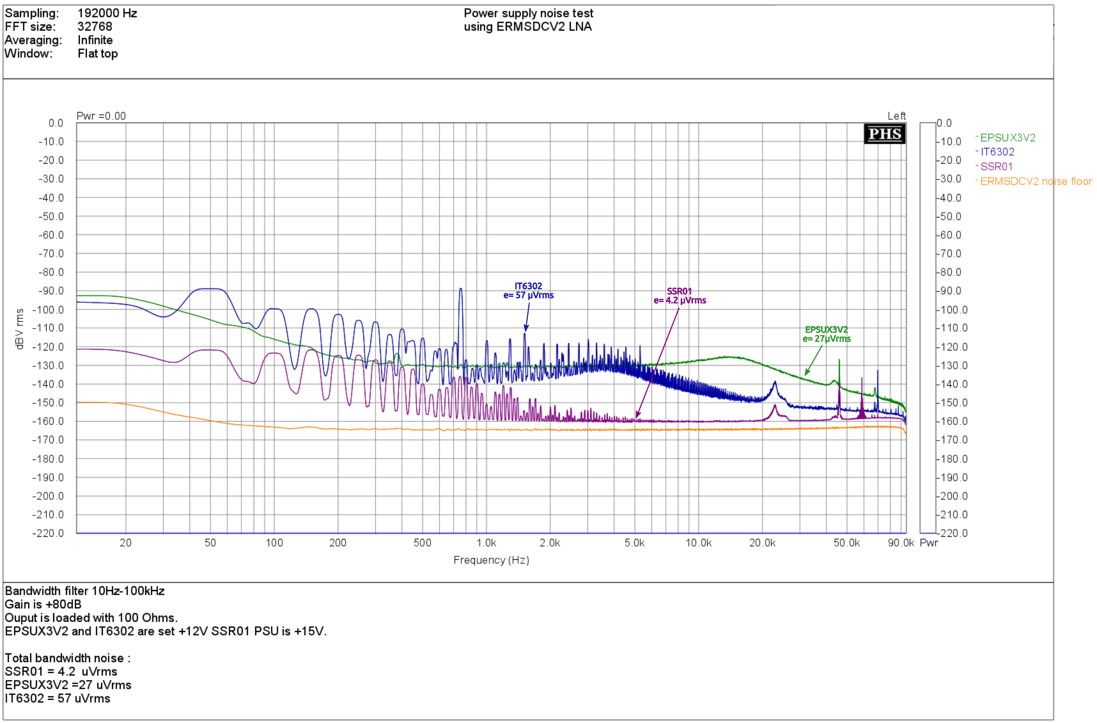
As we can see, they exhibit all a very low noise level.
The EPSUX3V3 show a very low noise level and clean spectrum (no spurious)
despite several switching stages and high power.
Even the low cost IT6302 laboratory PSU show also very good result with some main harmonics visible.
To finish the ultra low noise SSR01/02 PCB show excellent noise level and approach
the noise floor of test setup (so, it's fixed output voltage and somewhat fragile PSU).
Note : the others PSU hadn't been tested with ERMSDCv2, because overloading the input (noise > 1000uVrms).
So now, the noise spectrum of each output of the AAPSU01V1.
The test is made with unloaded output, and with 20 % of nominal load current (on each output).
(Note that all measurement are made without enclosure (PCB alone)
and without the SMD shielding cabinet soldered).
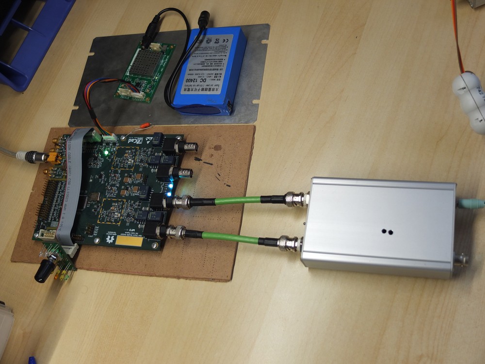
A picture of the noise test setup with the DUT (AAPSU01 PCB) , ERMSDCV2 LNA and EADCAKM ADC :
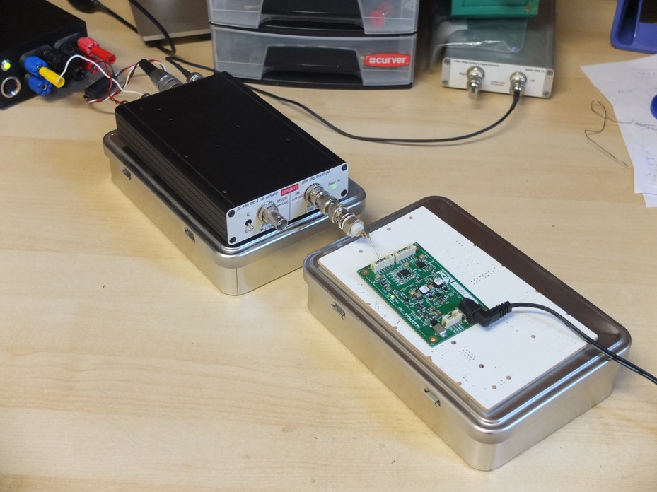
First, the DC input voltage come from a 12V Li-ion 12400 battery pack.
AAPSU01V1 noise spectrum with 12 BATTERY pack Li-ion :
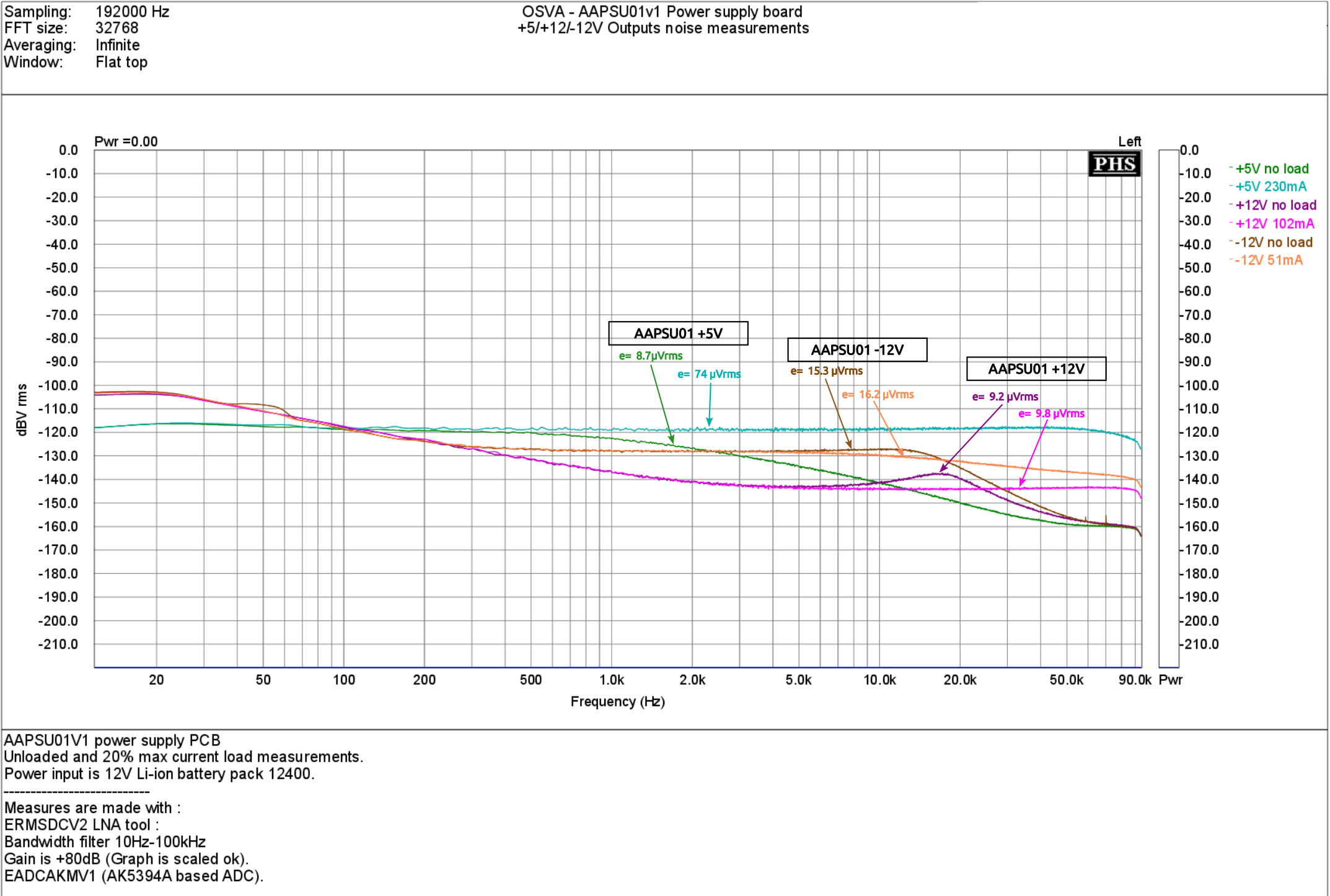
As we can we, noise level is kept very smooth without spurious in spectrum.
The measured values are very close to used low noise regulators specs.
Because it is important to show also how it work in a real harsh environment
with a poor wall adapter (SMPS), i made the same measurement but using the 12V
ENG wall adapter instead of the battery pack.
AAPSU01V1 noise spectrum with "ENG" 12V wall adapter :
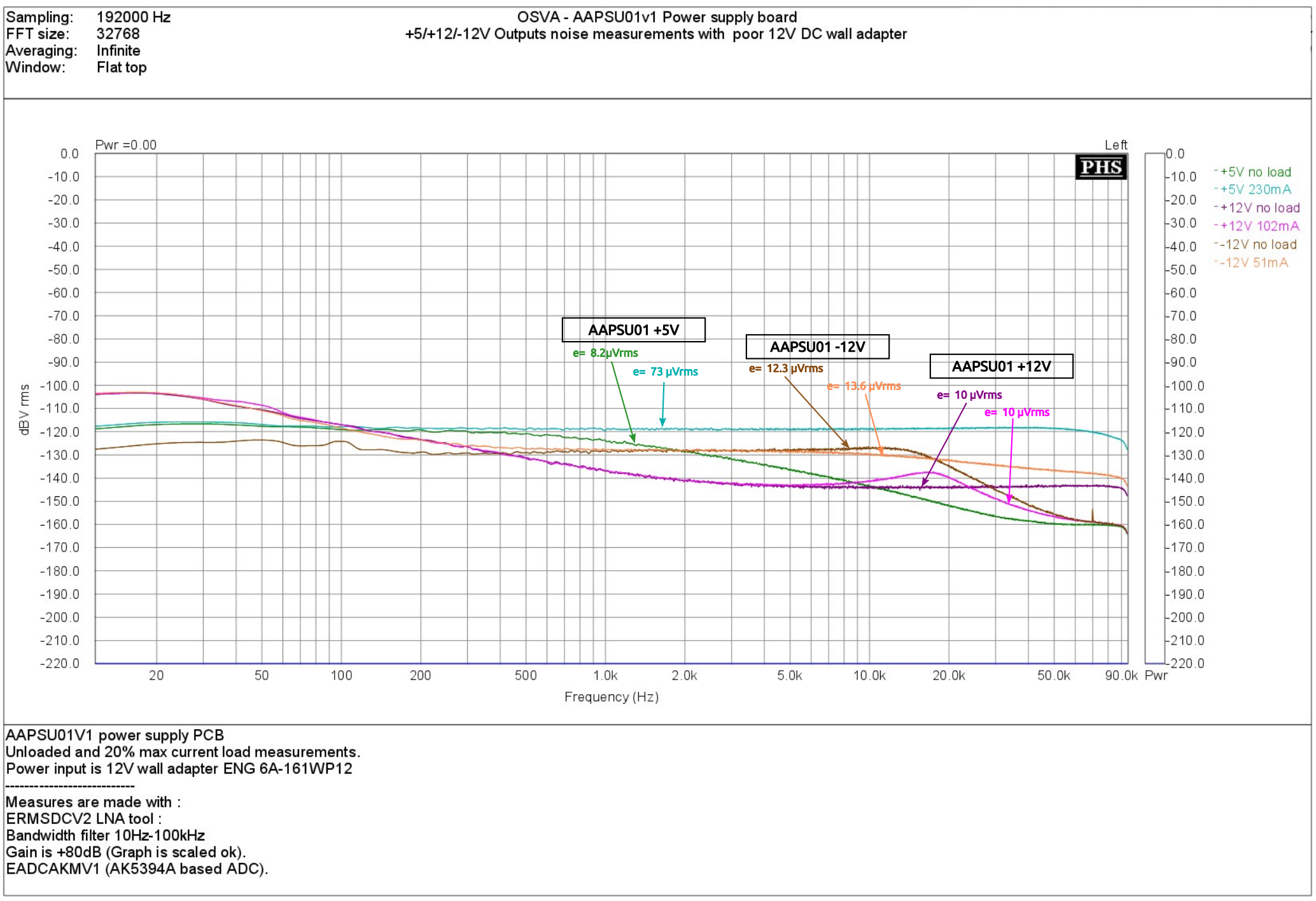
We can see that even with poor input adapter connected to main (230V 50Hz),
the noise floor still the same as with the battery pack.
We can also note that there is no added spurious in spectrum that prove
the excellent PSSR of the regulators.
These results let me very confidant to use it with the AA2380v1, LTC2380-24
ADC board without any risk of compromising signal integrity and then getting
full ADC performance.
So, now it's time to work harder in AA2380 CPLD software !..
Frex
Hello,
I made these days some tests on the AAPSU01v1 prototype board.
It include efficiency measurements on each outputs, and extended noise measurements.
The AAPSU01v1 has been test at full power (~ 15W) and work safely at this level.
(Note : +5V / 1.1A , +12V 500mA and -12V/250mA).
Because no thru-hole parts are required, if needed the PCB bottom side can be put
directly on aluminum panel to serve as heat-sink (with an thin insulted sheet to avoid short circuit!).
I measured overall efficiency for each outputs, for 12 and 20V DC input (all output loaded).
Results can be showed on graphs below :
The efficiency is not very high, but far better than a full linear PSU and considering
the size of board (80x50 mm) for this output power (15W).
Now, it's time to for serious noise measurements.
To begin and for reference, I made first some noise measurements
on different power supplies and for various measurement bandwidth.
I tested power supply listed below :
- _ ENG (6A-161WP12) 12V 1,5A wall adapter (jack out)
- _ ITECH IT6302 , entry level laboratory PSU
- _ SSR01/02 Ultra-low noise PSU (PCB's from Per-Anders Sjöström)
- _ EPSUX3V2 laboratory PSU (My own DIY design).
- _ Xiaomi MDY-08 USB wall adapter 5V 2A (phone charger)
- _ DIY old school LM7812 based 12V PSU
- _ and the AAPSU01V1 OSVA PSU PCB (of course !)
Below,some pictures of each DUT :
Xiaomi USB charger 5V and ENG 12V wall adapter
12V 12400 Li-ion battery pack and ITECH IT6302 lab power supply
EPSUX3v2 DIY power supply and SSR01/SSR01 +/15V ultralow noise PSU
Old school 12V PSU (LM7812 based)
I made the noise measurements using two methods (bandwidth) :
1) 10Hz-100kHz standard noise bandwidth measurements
(using ERMSDCV2 design : + 80dB low noise amplifier with 10Hz-100kHz pass-band filter).
2) 5Hz-20MHz Wide-band noise measurements using RACAL-DANA 9300F millivoltmeter.
These two measurements schemes allow to show noise contribution in various bandwidth
and then give more consistent results.
The graph below summarized the results (in linear and log scale of noise level):
Various power supply noise (linear scale) :
Various power supply noise (log scale) :
The picture below show noise spectrum for these various PSU :
(Note that there is only PSU with noise < 1mV to not overload the test setup of ERMSDCV2).
Various power supply noise spectrum in audio 10Hz - 100kHz bandwidth :
As we can see, they exhibit all a very low noise level.
The EPSUX3V3 show a very low noise level and clean spectrum (no spurious)
despite several switching stages and high power.
Even the low cost IT6302 laboratory PSU show also very good result with some main harmonics visible.
To finish the ultra low noise SSR01/02 PCB show excellent noise level and approach
the noise floor of test setup (so, it's fixed output voltage and somewhat fragile PSU).
Note : the others PSU hadn't been tested with ERMSDCv2, because overloading the input (noise > 1000uVrms).
So now, the noise spectrum of each output of the AAPSU01V1.
The test is made with unloaded output, and with 20 % of nominal load current (on each output).
(Note that all measurement are made without enclosure (PCB alone)
and without the SMD shielding cabinet soldered).
A picture of the noise test setup with the DUT (AAPSU01 PCB) , ERMSDCV2 LNA and EADCAKM ADC :
First, the DC input voltage come from a 12V Li-ion 12400 battery pack.
AAPSU01V1 noise spectrum with 12 BATTERY pack Li-ion :
As we can we, noise level is kept very smooth without spurious in spectrum.
The measured values are very close to used low noise regulators specs.
Because it is important to show also how it work in a real harsh environment
with a poor wall adapter (SMPS), i made the same measurement but using the 12V
ENG wall adapter instead of the battery pack.
AAPSU01V1 noise spectrum with "ENG" 12V wall adapter :
We can see that even with poor input adapter connected to main (230V 50Hz),
the noise floor still the same as with the battery pack.
We can also note that there is no added spurious in spectrum that prove
the excellent PSSR of the regulators.
These results let me very confidant to use it with the AA2380v1, LTC2380-24
ADC board without any risk of compromising signal integrity and then getting
full ADC performance.
So, now it's time to work harder in AA2380 CPLD software !..
Frex
Hello all,
I work hard these days to finish the first revision of the CPLD software
and to start to make some first serious measurements in next weeks.
I noticed also that the new MCH-streamer USB/I2S interface can handle
up to 4 x 384 kHz and so will allow to use it with the AA2380v1 OSVA
board as with USB-Streamer. So it would be possible then to send the
full sample rate of the ADC with sliced data.
To soon.
Frex
I noticed also that the new MCH-streamer USB/I2S interface can handle
up to 4 x 384 kHz and so will allow to use it with the AA2380v1 OSVA
board as with USB-Streamer. So it would be possible then to send the
full sample rate of the ADC with sliced data.
To soon.
Frex
Not really, while requires additional tweaks to run with an external master clock
Hp
Hi Frex,
I really this design and its performance.
On the GitHub page, I see Gerber files, KiCad files and BOM of AA2380 board---part of the OSVA project.
I am glad to see this, and planning to start order PCBs and start soldering work. However, I noticed that CPLD (5M570ZT100) software is not available.
Would this be available? I know perhaps it's on testing, but it would be awesome to release the code.")
Also, would you mind to make a simple guide of how to connect to SDR-widget?
I successfully finished soldering work and make SDR-widget work great, but I am a bit confused of connecting to AA2280.
In short, there are 2 problems I've met:
1. CPLD firmware
2. Utilizing SDR-widget as USB interface for AA2280
Best,
Erik
I really this design and its performance.
On the GitHub page, I see Gerber files, KiCad files and BOM of AA2380 board---part of the OSVA project.
I am glad to see this, and planning to start order PCBs and start soldering work. However, I noticed that CPLD (5M570ZT100) software is not available.
Would this be available? I know perhaps it's on testing, but it would be awesome to release the code.
Also, would you mind to make a simple guide of how to connect to SDR-widget?
I successfully finished soldering work and make SDR-widget work great, but I am a bit confused of connecting to AA2280.
In short, there are 2 problems I've met:
1. CPLD firmware
2. Utilizing SDR-widget as USB interface for AA2280
Best,
Erik
Hello Erik,
The current CPLD software is already available on Github here:
OneAudio/AA2380_MAXV
I work on it and so no final version yet available, but i update my work regularly.
About the SDR widget, it's not very hard to connect to the AA2380 board.
I will write a full guide but no time available right now, i will try to do it soon.
Diyralf, the CPLD allow mainly to read ADC values at various speed and
convert their serial SPI link in I2S form (for SDR widget and USB streamer)
and also in SPDIF link for direct connection to a computer sound-card.
It allow the use of the AA2380 board in stand alone board,
without the coming MAX10 board (AA10M08).
Regards
Frex
AA2380V1 first THD mesurements
Hello all,
I made some first measurements on the AA2380v1 ADC board of the OSVA.
I made them using the combo AA2380 ADC board and AAPSU01 power supply board.
The source of power is a 12V Li-on battery pack that supply AAPSU01.
I used my EOSC10Kv3 ultra-low THD in differential mode to send it to AA2380v1 input.
The full setup is show on pictures below :
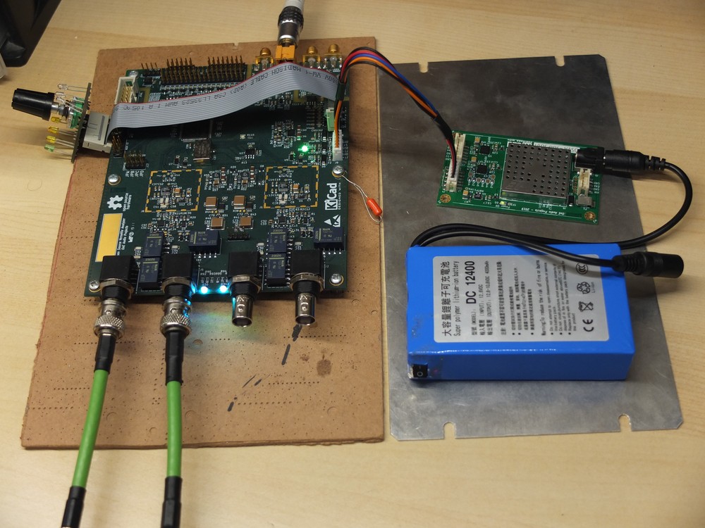
FFT results are below (lin and log scale).
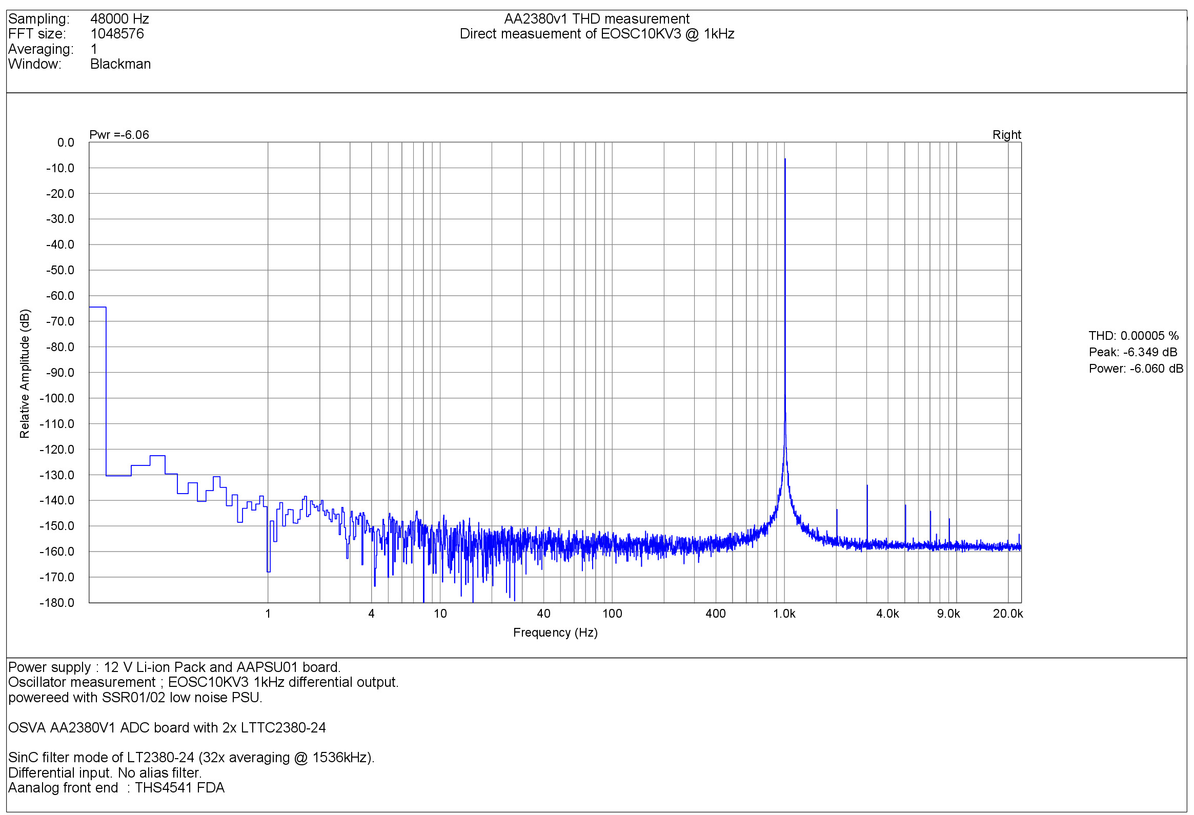
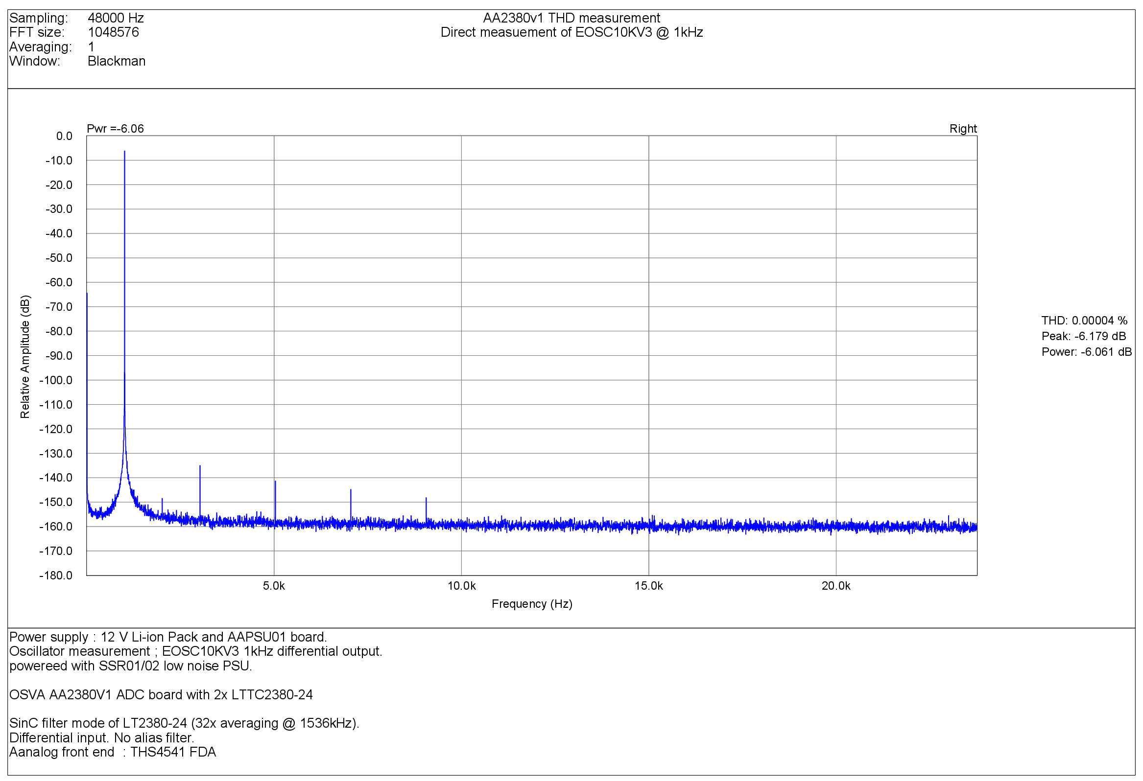
Results are consistent from what i had with modified EVM.
The FFT spectrum is amazingly clean, with no spurious other than THD product itself.
The lower frequency band show absolutely not any trace of main supply ! (no hum noise).
Note that there is no FFT averaging.
The THS4541 input buffer seem promising, but as the input stage can accommodate others, I will try them (ADA4945-1 and OPA1632).
Frex
Hello all,
I made some first measurements on the AA2380v1 ADC board of the OSVA.
I made them using the combo AA2380 ADC board and AAPSU01 power supply board.
The source of power is a 12V Li-on battery pack that supply AAPSU01.
I used my EOSC10Kv3 ultra-low THD in differential mode to send it to AA2380v1 input.
The full setup is show on pictures below :
FFT results are below (lin and log scale).
Results are consistent from what i had with modified EVM.
The FFT spectrum is amazingly clean, with no spurious other than THD product itself.
The lower frequency band show absolutely not any trace of main supply ! (no hum noise).
Note that there is no FFT averaging.
The THS4541 input buffer seem promising, but as the input stage can accommodate others, I will try them (ADA4945-1 and OPA1632).
Frex

- Home
- Design & Build
- Equipment & Tools
- OSVA - Open source Versatile Analyzer