Next steps-
1) take my 1" B&K and my pistonphone and calibrate it (a 124.1 dBSPL at 250 Hz) with a suitable readout (the B&K 2609 except I hate its indicator)
2) Then calibrate my 1652-A calibrator at 250 Hz to match the pistonphone -10 dB (-114) with the B&K 1"
3) Then calibrate the GR 1560-P3 on the 1562-A at 114 dB at 250 Hz
4) Then check the 1599B meter at 250 Hz on both scales with the calibrated microphone using the relative function of the Boonton or the Fluke 8922A which has a 10 MegOhm input.
Given all the transfers I would only trust this as +/- .5 dB but it would be a good reality check.
Lots of steps. And a very cluttered bench.
Update- I went through all the steps and there is maybe a .2 dB error on the level indicated by the meter on my 1559. I wish the meter and the system was spec'ed to 94 dB SPL. All my other calibrators are either 94, 114 or 124 (except the Omnical which goes down further in 10 dB steps. The 2 dB are missing and could lead to errors going from device to device. Otherwise it seems accurate. I will be doing the corrections etc. for higher frequencies at some point and that will be more challenging.
Actually I'm a bit nervous about running the internal mic at high levels, so I usually limit myself to 90 dB. Anyway, I think I've got the calibration sorted. Being an idiot, it took me a very long time and some false starts. I'll be updating the spreadsheet soon. Everything now seems to agree within about a needle width on the meter. The only question is how good the basic reciprocity measurement is, because that's where everything starts, but I have a fair amount of confidence in it.
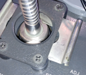
The microphone I got, a 1560-P4, is an exact fit in the space. No adapter needed. It shows how the clamp is intended to work and why a Delrin adapter would need the rounded edges.
I'm still working through the differences in calibration references and how to translate as well as the insert voltage stuff. I think I have most of what is needed except an adapter cable and an adapter sleeve to do a calibration of a B&K. The high frequency stuff is also a challenge to work out.
I'm building a high voltage amplifier for driving this using an Apex PA85 and a DC-DC converter off of eBay to power it. Because of the high voltages I'm not rushing.
Attachments
I remain unconvinced on the clamp. I think it's just a tad too low, and should slide fully home without undue stress. Mine was actually bent from somebody trying to force it and it took me some time to get it working smoothly again. I also wonder if all the different mics have the same length? That would seem too good to be true, or maybe washers came with the adapters? Were there any 1/2" adapters made? Let me know what you need for the B&K mic.
The RATIO between acoustic chamber volume and capacitors capacitance is what makes this instrument a primary calibrator. If they are wrong, so it is a measurement. If the capacitor is off by a 0.5% then the measurement is also - but only a fraction of the dB (20 log (1.005/1)) .
I think the frequency limit is partially because of the mic diameter. When I read about mics for loudspeaker testing, they say anything above .5" diameter will be limited on high frequency performance. I was surprised to see that 1" mics are really 0.936" +/- 0.002". Kinda like a 2x4.
I have a question about couplers and cavity volume. I know the volume has to be accurately known for the reciprocity measurement, but when just using it (or a regular calibrator/pistonphone) as a source, how critical is the volume. IOW, do adapters have to put the mic face in just the right spot, or is the cavity SPL valid over a range?
Only the volume is important, if the ratio dia/l is within some limits. And also capacitance of the 0.9uF capacitor. Everything else is ratiometric. Even the input voltage is not critical.
Much better- everything agrees now. I don't understand they they offer two ways of exciting the cavity, the reciprocal mic and the PZT cylinder. They both seem to rely on the meter calibration and ultimately have about the same accuracy, but that Bonk was a clever fellow, so maybe I'm missing something with the calibrated mic method. Anyway, thanks for the measurements! Now I can stop obsessing over this thing, at least a little.
It is like calibrating the gain of antennas. You need three, to calculate three pairs of electrical sensitivities, and through matrix calculation (three-cornered hat method) finally individual sensitivity.
The same goes for free field microphone calibration- You also need three.
Here, free space loss is simulated by chamber in acoustical chain, and capacitor in electrical. Difference of logarithms of those two losses is final sensitivity.
Logarithm is done through analog computer - that big potentiometer with its hardware and scale...
Measurement uncertainty depends on the ratio of the volume and capacitance , and correctness of this log-log calculation.
Bruel and Kjaer device is basically the same, only calculation of sensitivity is computerized......
Last edited:
Those are probably the same scans as on the jptronics site. If your B version is a later one, I'd love to see it.
I'm sure I can fix you up with some adapters. Email or PM me with what you need.
I'm getting stable results now and part of the secret is having a high impedance detector with low capacitance- the cable is important. That might be why they supplied a cable with the instrument. Use low C cable and keep it short. I even pondered putting a little FET buffer inside the XLR connector, but that's probably overkill.
I'm still not positive about the best way to calibrate the internal pots and position of the wiper/small knob. It's close, but I think better is possible. My present understanding is that achieving an accurate SPL requires that the attenuator produce an exact voltage. That seems to depend on the meter calibration, which depends on the PZT tube sensitivity. OTOH, that may be why they have three pots when two would have been enough for just the meter. Still thinking about it. Remember that all GR equipment was capable of better performance than the published specs. It wouldn't surprise me that with careful setup, this might be good to .1 or .2 dB.
PZT tube sensitivity is not a critical factor here. It is just one of the three microphones. Math takes care of any variation of its sensitivity.
Potenciometer also has some finite resolution, and also beginning of the scale , but that is all sub dB...
I figured out the reason for difference adapters for the GR (WE, HP, Gefell) 1" (.946') microphones and the B&K mikes. The core comes from the different grids on them. The original WE640AA has a retaining ring on the front and the diaphragm is recessed. it was not designed as a measurement microphone but worked well for that application. The WE, GR, HP and Gefell microphones copied the WE grid, with a flat face with a hole pattern on it. B&K redesigned the structure with the diaphragm closer to the front surface and no retaining ring. The "famous" B&K grid was to allow off axis response to better match the grid off and has the openings down the side. The adapters for the GR type grid won't seal properly on a B&K microphone. The B&K adapters will have an o-ring to seal behind the grid. There is also a difference in the front volume between the WE and the B&K that would require spacing the microphone back a little to correct or correction values (the Omnical manual has a lot of correction values and matching confusion. . .). I have not seen this specifically documented at all except in an old writeup in the B&K journal.
Now I can move forward with some of what I want to do. I'll still need some adapters. I'll PM Conrad with what I need. Details on the 1559-6080 would be interesting since I can't find references to it.
Now I can move forward with some of what I want to do. I'll still need some adapters. I'll PM Conrad with what I need. Details on the 1559-6080 would be interesting since I can't find references to it.
- Status
- This old topic is closed. If you want to reopen this topic, contact a moderator using the "Report Post" button.
- Home
- Design & Build
- Equipment & Tools
- Got a GR 1559-B Microphone Calibrator