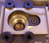
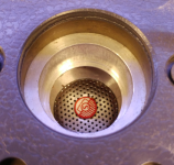
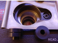
Here are some closeups of the clamp assembly dismantled. And of the opening. This opening is 1.125" ID with a thin flange at the bottom the mike would sit against. Its dimensions are consistent with the first gen GR microphones 1560-P1, 1560-P3 and 1560-P4 1 1/8" (1.125") microphones. The notes indicate they it comes with an adaptor for the 1560-P5, 1560-P6 and the WE640AA and B&K 4131 condenser microphones.
Yours may have the adaptor in place and that's part of the issue. What I need is a version of that adapter for the 1" (.936") (GR part number 1559-6080). It suggests its just a sleeve (see pg 6 of the manual).
From your description of the unit there may be some corrosion holding the sleeve in.
Reading through the directions I think I could use one of my Boonton 1120s for all the process. They have a sensitive meter that can reference a level and up to 16V across 50 Ohms to drive the piezo element.
Using it with a B&K will be more complex BUT I do have a volt insert adapter I just need to adapt to this.
Attachments
Wow, that's nothing like mine! You may be right, I may have an adapter stuck in there, but I didn't notice a parting line where the adapter would end, and what you show there, begins. I'll have another look tonight and see if I can get a decent photo. BTW, is yours an A model, sans the 4-position range switch, or the B model like mine? Thanks!
Edit- Holy mother of stuck stuff! I got it out and now it looks like yours. It wouldn't move at all, so I slipped a couple drops of alcohol down the edge and worked it sideways until it moved a thou or so. Then I just kept on and eventually it started to move. The "sleeve" is a bit more complex than that, but nothing hard to make unless you include the three ball friction devices. Those are held by an O-ring, that probably also made the thing impossible to move. I'll make up a detailed drawing of the thing. If you have access to a lathe, it should be easy enough, or if you can wait until spring when my garage thaws out, I'll make you one. I think with a little polishing and a light film of lube, mine will be much easier to get in and out. BTW, it does have a long groove down the inside to vent the chamber, until near the very end, where it stops and seals. Not sure how they did that, maybe a shaper, but it would take a very special milling cutter to duplicate it- tiny ball end on a long shaft.
Thanks again!
CH
Last edited:
No lathe here. Too much other stuff to grab my attention. I would make the sleeve from delrin. Less likely to freeze and otherwise the same as the ones B&K provide with the pistonphone. I would need a slightly different version I think since I would need it to work with the B&K microphones and the voltage insert adapter. That will be my bigger challenge for now. Per the instructions I need to remove the grid on the microphone (always scary). I checked the insert adapter I have and that won't fit. But I may be able to modify a mike preamp to support the insert voltage necessary for this project.
Just so I can get this moving I found a GR1560-P4 microphone on eBay and it should be here in a week or so. I will be able to get the system up and running with that as a starting point. It has the larger diameter so no sleeve needed. The example even has an O-ring on it for some reason.
I may be able to get this thing useful yet. it will be a process of learning from the basic to working with new microphones.
Can you take some pictures of the sleeve? One issue would be compensating for chamber volume. The B&K adapters for the pistonphone has cavities to add chamber volume to compensate. They may be overkill on this level but .1 dB is essentially 1% so all these details become important. B&K's software gets inputs for pressure, temperature humidity microphone front cavity volume etc. And a single calibration for one frequency can take over 1 hour. The GR won't measure to less than .1 dB and even that is probably not fully valid but still all these issues are important.
Of things to make it out of, aluminum is out because it would seize up unless anodized. Still not my first choice. The factory one looks like it's nickel plated, so maybe brass, possibly steel. Expensive these days. Delrin would be great so long as the tolerances don't let it jam up on a warm humid day. Delrin is good, but not as dimensionaly stable as metal- it would still be my first choice. Or 303 stainless. I just don't have a lot of large material around. When I get a free moment I'll do a dimensional drawing and take some photos for my page.
I saw that mic on eBay but passed because I've already got a few. Not a clue what that O-ring does, unless it's just for protection when setting the mic down on a hard surface.
I saw that mic on eBay but passed because I've already got a few. Not a clue what that O-ring does, unless it's just for protection when setting the mic down on a hard surface.
Looking at some common implementations Delrin with O-rings seems to be the current solution until you get to the highest tier. B&K uses Sapphire cylinders specific to each microphone type in their latest reciprocity setup. I refuse to be an "acoustic calibration nut" at that level. I'll leave that stuff to NIST. Getting a repeatable 1 dB in a room is almost impossible anyway. I'll just be satisfied when I can calibrate my calibrators +/- 1 db. . .
Sapphire! No thanks. I bet B&K stuff is really nice, but affordable to very few. Wonder how much their reciprocity calibrator costs? I have an adapter for a $5k Quest SLM (0.520" B&K mic to 0.936" calibrator) at work and it's just black molded plastic, probably styrene or similar. It was a class 1 meter but unfortunately it got dropped and the 4936 mic was destroyed. No $$ for a new one.
The current reciprocity system from B&K https://www.bksv.com/media/doc/bp1697.pdf is really a national standards lab type thing, like getting your own Josephson Junction array as a voltage reference. The only thing more expensive is the staff to operate it.
This would be much too daunting: https://www.bksv.com/media/doc/bn0725.pdf
Maybe you can get them to spring for a used mike. That would be an electret type I think. Fortunately they are usually interchangeable if the same size.
This would be much too daunting: https://www.bksv.com/media/doc/bn0725.pdf
Maybe you can get them to spring for a used mike. That would be an electret type I think. Fortunately they are usually interchangeable if the same size.
Even after cleaning everything, and removing the o-ring, the adapter is quite difficult to insert and remove. Very little clearance and any dirt or corrosion would make it near impossible. Sort of like it was. Anyway, here's a drawing with some decent dimensions. If I were to make one, I'd knock off a thou so it wasn't so tight. Photos when I get a chance.
Attachments
Last edited:
Polished it up with the Simichrome and applied just a shine of Superlube PTFE grease and now it moves freely.
It occurs to me that most of the features aren't necessary. The o-ring does nothing but load the little balls. I don't think it seals on anything. The whole larger top section is just the way they continued from the o-ring groove. A plain Delrin sleeve with the lip at the bottom and relief on the end would probably work just fine.
The remaining problem I'm having is inconsistent results from session to session. It seems I get the same sensitivity numbers are any given session but can't repeat them day to day. I notices this from the first time I used it. Range is about 1 dB or a bit less. I'm wondering if I should try some contact cleaner on the switches?
Having looked at the switches it seems unlikely they are the cause. First check the connectors and maybe some Caig contact stuff would help. I believe the connectors have silver plated contacts so they could be pretty compromised. Temperature, air pressure can both have an impact as well. The fit of the microphone and airtightness of the chamber is the first issue. Have you confirmed the stability of the indicator? It should fall out of the numbers but. . . And the stability of the microphones and the transducer could be an issue. In reality 1 dB is good but this should be closer to .1 dB.
I think a Delrin sleeve should be fine. Adding grooves and O-rings would make it ideal. I need to do some research on how the system works with the condenser microphones.
They say to use it without a grid but the more I research the more confused I am. NIST offers both depending on how you intend to use the microphone. B&K actually measures to 50 KHz for the 1" microphones even though they are rated to 8 KHz as pressure microphones. The current B&K system for free field works the same as a speaker measurement with a windowed response. I may need to bring out the cap connections so I can make similar measurements.
You might find this interesting- https://jcaa.caa-aca.ca/index.php/jcaa/article/viewFile/488/157 Their means of determining volume was pretty clever and easy to implement.
A search on one or both authors yields a lot, but I don't have access to the professional journals.
A search on one or both authors yields a lot, but I don't have access to the professional journals.
Initial tests say the 1559-B is probably fine, but one of my mics has a problem. The sensitivity seems to move around by 1 dB or so. I'm going to rewire it, but my guess is something happened to it, maybe dropped in the past or just old. It's my only non-gooseneck mic, so was convenient enough that I'll probably find another one.
Turns out I have scans of both a and b versions of the manual. They have very similar content. Let me know if you need either.
I'm looking at how to modify a preamp to work with this for calibrating a condenser microphone. I have HP preamps and an HP SLM that are somewhat compatible. I'll need to get some Delrin adapters made but from there on this will be pretty straightforward I think.
I'm looking at how to modify a preamp to work with this for calibrating a condenser microphone. I have HP preamps and an HP SLM that are somewhat compatible. I'll need to get some Delrin adapters made but from there on this will be pretty straightforward I think.
Those are probably the same scans as on the jptronics site. If your B version is a later one, I'd love to see it.
I'm sure I can fix you up with some adapters. Email or PM me with what you need.
I'm getting stable results now and part of the secret is having a high impedance detector with low capacitance- the cable is important. That might be why they supplied a cable with the instrument. Use low C cable and keep it short. I even pondered putting a little FET buffer inside the XLR connector, but that's probably overkill.
I'm still not positive about the best way to calibrate the internal pots and position of the wiper/small knob. It's close, but I think better is possible. My present understanding is that achieving an accurate SPL requires that the attenuator produce an exact voltage. That seems to depend on the meter calibration, which depends on the PZT tube sensitivity. OTOH, that may be why they have three pots when two would have been enough for just the meter. Still thinking about it. Remember that all GR equipment was capable of better performance than the published specs. It wouldn't surprise me that with careful setup, this might be good to .1 or .2 dB.
I got the old microphone and spent some time exploring calibration. I mde progress and found a number of hiccups to sort out.
First, the sensitivity pot seems to have its shaft connected to the pot wiper. The net effect is almost .5 dB shift when I hold my hand near it. Is that correct or a fault?
Second, I added a quick translation chart for microphone sensitivity since some are specified in dB and others in milliVolts. This translates between them Its the last tab in the updated sheet.
Attachments
Last edited:
I'm getting pretty consistent results now. One mike so it doesn't mean a lot. lessons learned- read the manual and look for clues and details. Things that were not entirely clear like a 600 Ohm source impedance for the drive and min 5Meg input for the meter. I set up an amp and transformer to get the 50V and power resistor in series to get the 600 Ohms. Tried several preamp solutions but the B&K 2609 measuring amp worked the best.
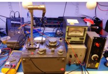
I'm using the HP467 amp into the Optimation stepup transformer to get the drive signal. Not shown is the Boonton 1120 analyzer that make the process pretty quick. It has a relative function for level, reads out to .01 dB and has a really nice source to drive the amplifier. In checking the source might need to provide as much as 3W of power.
Next steps- figure out how to fit a condenser preamp into this chain with the voltage insert capability. Then sketch out the adapters for 1" and 1/2" mikes. And to build my calibration interface setup. but at least I have it running after 10? years in my collection.
Attachments
Wow, your test bench looks a lot like mine. I've been exploring calibration and change my worksheet on a daily basis. I think I understand it, but haven't been 100% successful yet.
The internal pots allow adjustment over a very limited range, save for the 5k. My logic is the 5k pot is only in-circuit for the Read functions, so it can always match the meter reading to the cavity SPL. Where I have a problem is the Adjust. Only the two meter range pots are in-circuit there, and they only cover a couple dB. Note that in Adjust mode the meter is reading 1/2 the voltage if the generator is truly 600 output Z. If my calibrated GR mic is telling the truth, my PZT tube achieves 92 dB SPL at well under 50 volts, more like 44. That means I can't quite match the Adjust 1 reading to the Read 1 reading because the pots don't have the range.
Several possibilities. 1) It may not matter. As long as the log pot wiper is correctly positioned, everything should work. 2) My calculation for the mic voltage could be wrong. I measured the capacitance of the mic and of the cable and meter, but I need to verify using a preamp or maybe 10X scope probes. 3) My PZT tube might be too sensitive- aging? 4) GR had some other plan in mind, though the pots don't have the range to set -6 dB either.
Watch your shielding. Even a short exposed section of wire will pick up enough hum to shift things slightly. I need to buy some proper XLR connectors. I haven't noticed proximity effects with the knobs/shafts. Because I update my spreadsheet often, and the early ones were pretty confused, be sure to grab a new copy. I tend to make lots of mistakes quickly, and correct them quickly, so let me know what's not yet right!
I see you found an adapter for the mic.
Your zip file seems empty, or I'm doing something wrong. BTW, did you notice I gave you credit on my web page?
Last edited:
Thanks for the mention. The Zip was empty. I need to fix per the following realization:
Next round of confusion. The instrument reads in dBV/microbar. Microphones are usually calibrated in terms on mV per Pa or dB per Pa which is 20 dB different. (My head hurts. . .) Lots of room for error for now.
The mike I'm using has a 1.125" diameter and is a fit in the default opening. The next steps will be to check it against some other standards to see if I'm getting meaningful measurements or nonsense.
Here is what I got measuring today. Next step is to compare against a known standard.
100 Hz -60.0 dBV
250 Hz -59.9 dBV
1 KHz -59.2 dBV
3 KHz -58.2 dBV
- Status
- This old topic is closed. If you want to reopen this topic, contact a moderator using the "Report Post" button.
- Home
- Design & Build
- Equipment & Tools
- Got a GR 1559-B Microphone Calibrator