Demian - That charge amp will be an asset for doing modal testing. Endevco makes some nice equipment. I'll have to say, though, that the 2775A is a lot bigger than it needs to be compared to what else is out there, but the price is right if it stays that low (and is working)! The link that wouldn't open earlier is now the above post. I just copied and pasted it. I hope I didn't break any copyright stuff. Anyhow, I give Endevco full credit for what I posted there.
I have a considerable collection of different charge amps for doing calibration on the hammers and accelerometers that I'm building. My goal in this forum is to try and make it as simple and cost effective as possible for speaker builders and others interested in trying their hand at modal testing. Therefor, I'll keep taking short cuts and reduce the need for extra electronics where I can.
The plain vanilla spreadsheet method of data entry is clunky, but serviceable if it's plotted as a surface. An experimenter can move on from there depending on one's interest and budget.
I'll continue to post my overly simplified approach to how modal testing can be done and hopefully some readers will get a notion about how powerful this method can be as a design and measurement tool.
Demian - What were you planning to use for a charge amp and accelerometer? It looks as though you may actually be able to do some testing. It would be interesting to do some comparisons between a microphone and the accelerometer responding to the same stimulus. It should be quite informative even without an instrumented hammer.
The intention was to better understand everything from cabinets to drivers to turntables. But the very limited knowledge and many other things I'm dealing with left this sitting on the sidelines. I also have an optical vibration sensor, an older MTI Fotonic I got to look at cones and domes. Still not implemented. I even have a Endevco mike I picked up in passing.
Learning more about the relationship between panel vibration and acoustics is very interesting. The limited stuff in Stereophile has been a tease but mostly useless.
The software is the most challenging part. I have acoustic software but nothing to breakdown panel modes etc.
Learning more about the relationship between panel vibration and acoustics is very interesting. The limited stuff in Stereophile has been a tease but mostly useless.
The software is the most challenging part. I have acoustic software but nothing to breakdown panel modes etc.
Rod Elliott put up a web-page devoted to accelerometers in November 2018:
Project 181
Project 181
Thanks for the link to the Project 181 article. It's reassuring to know that there are others out there that are experimenting with direct vibration measurements using accelerometers. A lot of things were discussed there that saved me the effort of trying to describe the advantages of this type of testing.
One thing that should be included in the overall scheme of things here is that a modal hammer is a significant hardware addition for making good measurements. The Endevco article posted above covers most of the bases, hopefully, for the more adventurous speaker builders.
I was surprised at the cost of the commercial hammer offerings out there. Even the used ones on eBay are pricey. I design and build a lot of different instruments for my experiments so it was easy to decide to build my own instrumented hammer. Now I have a much better understanding of why they want so much for one.
The hammer as such is easy enough to machine. Building a good force transducer that will work properly as a modal hammer is a whole other thing. I'm now on my 5th generation and things are finally coming together. I'm about at the same stage with the accelerometer.
When the designs are finally solidified my plan is to offer up a hammer/accelerometer combo on eBay and see what happens. Sort of casting my bread on the waters. It will be an entry level offering that should be attractive to the educational market for budding engineers that want to learn modal analysis, but can't afford the instrumentation from the Big Guys. It might get some speaker builders interested along the way, too.
If nothing else I'll at least have my own set up and will have learned a lot about vibration transducers and measurements. I appreciate the company of those readers who have chosen to follow along.
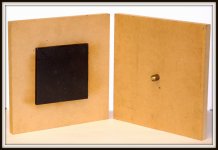
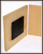
Here are some simple tests done with the hammer/accelerometer pair. I used a piece of 3/4" MDF that was available for cutting into 2 - 1ft square panels. The accelerometer was attached with a dab of bee's wax to center of each panel during the test. The wax makes a good attachment method for this type of testing and it's easy to remove after testing. Low temp hot melt glue works well, also. The base of the accelerometer is magnetic for easy attachment to magnetic surfaces. The accelerometer design incorporates a magnet circuit to magnify the holding force. This design leaves virtually no field leakage to surrounding surfaces.
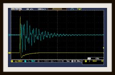
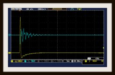
The DSO images were acquired with no charge amplifiers in the circuits. The signals are straight into the scope's channels. The top image shows an average of 4 taps with the hammer about 1" from the accelerometer. This activates a some modes of panel vibration that are easy to see with the accelerometer's signal which is also averaged 4 times. The averaging just levels the playing field for the stimulus/response evaluation. Both panel were placed on the same piece of very soft 2" thick foam for testing.
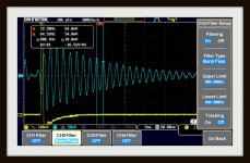
The second DSO image is with the accelerometer moved over to the center of the other panel. This panel has had a 6"x 6" piece of 3/8" thick damping material applied. It was just glued on with some 3M spray adhesive. The hammer was tapped approximately the same distance away from the accelerometer as in first panel test. The damping material was glued onto the opposite side from the accelerometer and tapping.
The amplitude of the averaged hammer taps indicates the force that the panel was tapped with. The averaged accelerometer output amplitude is the response to those taps. The difference between the 2 panel tests should be striking (pun). I know that I'm probably preaching to the choir, but this is stuff that's very hard to do with a driver, microphone, and a single panel in a test set up. Nuff said.
Hopefully, this post demonstrates that useful numbers can be generated from very simple tests that are relevant to speaker building. I'll continue posting these experiments if anyone is interested in a higher level of involvement in these simple modal testing methods.
The DSO images were acquired with no charge amplifiers in the circuits. The signals are straight into the scope's channels. The top image shows an average of 4 taps with the hammer about 1" from the accelerometer. This activates a some modes of panel vibration that are easy to see with the accelerometer's signal which is also averaged 4 times. The averaging just levels the playing field for the stimulus/response evaluation. Both panel were placed on the same piece of very soft 2" thick foam for testing.
The second DSO image is with the accelerometer moved over to the center of the other panel. This panel has had a 6"x 6" piece of 3/8" thick damping material applied. It was just glued on with some 3M spray adhesive. The hammer was tapped approximately the same distance away from the accelerometer as in first panel test. The damping material was glued onto the opposite side from the accelerometer and tapping.
The amplitude of the averaged hammer taps indicates the force that the panel was tapped with. The averaged accelerometer output amplitude is the response to those taps. The difference between the 2 panel tests should be striking (pun). I know that I'm probably preaching to the choir, but this is stuff that's very hard to do with a driver, microphone, and a single panel in a test set up. Nuff said.
Hopefully, this post demonstrates that useful numbers can be generated from very simple tests that are relevant to speaker building. I'll continue posting these experiments if anyone is interested in a higher level of involvement in these simple modal testing methods.
Attachments
What I see is about a 6 dB reduction in level and about the same frequency and decay time. However it would show if you managed to mechanically damp or null the natural frequency (eigemode?) of the panel.
Need directions for making the hammer. Even on eBay the price is crazy.
Need directions for making the hammer. Even on eBay the price is crazy.
Demian - Thanks for your observation and comment. You're correct that this method of measurement would be able to show any improvements in areas such as nulling or damping of panel vibrations. The ability to select the best choice of structural and damping materials before beginning a speaker enclosure project would be very helpful.
This measurement technique is also very useful for the assessment of already built enclosures that can be improved or modified with or without the drivers installed. As demonstrated in the above post useful information can be collected using only a common 2 channel DSO. Much more insight can be had by utilizing readily available frequency domain instruments.
Avoiding the inconvenience and ambiguity of trying to use a driver/microphone arrangement as a stimulus/response measuring technique can save many hours of frustrating work for any serious speaker builder.
I thought that it might be interesting to see what applying a simple bandpass filter would look like on a hammer tap using the same set up as described in post #28. These taps were done on the undamped panel. There was no averaging nor any attempt to reproduce the previous tests.
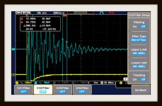
These 2 DSO images only show different taps with and w/o the filter. Channel 1 is unfiltered so that the force of the taps can be judged to be ~ equal. There was no attempt to be quantitative here, just a filter demo to show how a DSO measuring in the time domain can be used in these tests.
These 2 DSO images only show different taps with and w/o the filter. Channel 1 is unfiltered so that the force of the taps can be judged to be ~ equal. There was no attempt to be quantitative here, just a filter demo to show how a DSO measuring in the time domain can be used in these tests.
Attachments
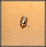
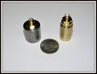
This is a comparison of the 5th generation brass housing accelerometer along side of the previous 12L14 steel housing unit. The mass has dropped from 23 grams to 11 grams. The output signal levels are about the same, but the bandwidth on the new one is better.
The modal hammer is still being refined and everything still needs to be calibrated. When the designs have all pretty much stabilized I'll be able to offer up some real numbers about the capabilities and limitations of these 2 instruments.
Please excuse the focus. This camera seem to have a mind of it's own when it gets near my bourbon.
Attachments
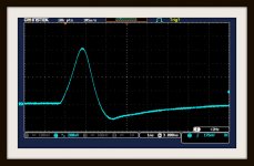
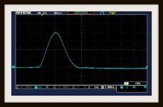
Now that I'm beginning to look at the modal hammer and accelerometer transducers more seriously it's time to start doing some measurements using charge amplifiers. These 2 DSO images are of the hammer tapping the same MDF panels as before.
The first image is of the hammer's signal going straight into the DSO's channel 2 input. As can be seen (and demonstrated in an earlier post) the half sine wave has been corrupted by the 1 megohm input resistance. The signal's amplitude is also attenuated. The signal has been averaged 4 times.
The second image is of the hammer having been passed through a very high impedance charge amplifier which allows the full signal from the hammer's force transducer to be collected and displayed undistorted by charge leakage. The charge amplifier has a low output impedance and can be adjusted to produce a calibrated force output signal to the DSO. This signal has also been averaged 4 times.
Attachments
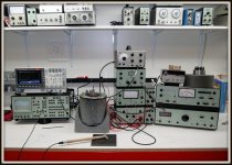
The modal hammer and accelerometer project has been moving forward slowly as I gather more instruments that apply directly to vibration measurements and calibration. The vintage Bruel and Kjaer stuff is really nice to work with and very well thought out for the application. My instrument bench for this project has been slowly growing over the years by patient collecting of B&K sleepers on eBay.
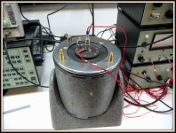
The present calibrating accelerometer is a modified general purpose Endevco device that I've attached a 12L14 steel cap onto with epoxy. This allows my magnetic base accelerometers to piggyback the bottom unit for simultaneous signal comparison.
The mini calibration shaker project is still in the works. It's prototype is designed to produce a 1g acceleration at 120Hz.
Attachments
As a potentially interesting aside to the hammer/accelerometer project I'll offer up a speaker panel test that can be used as a thought experiment relating to the application of modal analysis.
Since a panel is a simple type of structure you only need to choose how many measurements to make and where to make them. The rule here is that there is no rule about exactly where and how many measurements to use. Good judgement comes with time and some thought. Too many measurements take up unnecessary time and add complexity. Too few can lead to spacial aliasing that leads to inaccurate results.
Wave lengths can be empirically evaluated by changing the the distance between the accelerometer and the hammer tap. When the signal from the fixed accelerometer point has gone through a 360º phase shift from the original tap position the frequency can be determined by simply measuring this distance. Measurement points made at 1/4 or less of this wavelength should give good results.
This is a very simplified concept of how modal analysis can work, but speaker panels aren't really complex structures to evaluate using this type of measurement.
I have a GR 1557 calibrator somewhere I my stuff. I'll dig it out. Its a pretty clever design.
http://www.ietlabs.com/pdf/Manuals/GR/1557-A Vibration Calibrator.pdf
http://www.ietlabs.com/pdf/Manuals/GR/1557-A Vibration Calibrator.pdf
Thanks for the link to the GR calibrator. I'm a big fan of their instruments and have collected many pieces over the years. Their audio measuring and calibration instruments were second to none in their day as were all of their instruments. The build quality was as good as anything available then and it's still a pleasure to open up the cased and have a look inside.
Then came WW2 and HP pushed GR out of the way for the most part. Post war B&K came along to push HP pretty much to the side in the areas of sound and vibration instrumentation, though HP held their ground in some of those areas that the military wanted to support. Still, B&K is the best of equals when I have my choice for some types of measurements.
So much for reminiscing. The GR 1557 is a nice design and elegant in execution. I'm using a somewhat similar design, but with a compressor amplifier on the pickup coil. There's nothing novel about that. My choice of 120 Hz as the drive frequency is because its twice the line frequency and can be easily had with an unfiltered full wave bridge rectfier. The frequency is stable and constant enough for entry level accelerometer calibration.
- Status
- This old topic is closed. If you want to reopen this topic, contact a moderator using the "Report Post" button.
- Home
- Design & Build
- Equipment & Tools
- Enclosure vibration measurements