I do not know if I understand the monitor output correctly enough.
Have not re-opened the unit (since initially after arrival) but I intend to start with taking a look at TP100.
It looks like there is a common chain of resistors there and I am suspicious of R100 or R101 perhaps having incurred damage. (S4C)
It's early morning here and have a long day ahead of me so may not get around to take a look today. Knobs are still stuck at senders Post Office location so will not see these today either.
Last edited:
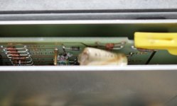
Oh, oh, does not look right
Opening the bottom up I saw this capacitor....
Now how to get the board out since the removal lug on the other side has broken off and this side is not much better too....
Got it out, not too bad to remove.
Opening the bottom up I saw this capacitor....
Now how to get the board out since the removal lug on the other side has broken off and this side is not much better too....
Got it out, not too bad to remove.
Attachments
Last edited:
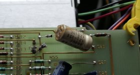
C27 and C26 were both replaced with 33uF, not 22uF. I cannot locally get 650uF so used two 330uF parallel and I replaced the 33uF with 22uF. There have been some other capacitor replacement as well and soldering is shocking. Some IC's now have sockets and one IC was not even seated properly.
Not pleasant but one has to remember purchase price and that shipping from other location outside New Zealand runs between 150 USD and 200 USD. Knobs are costing me about 70 USD but if I can resurrect then it may still be worthwhile for the few occasions I need it.
Voltage across the 650uF (actually measures about 664uF, still within spec's) is about 3.6 V so suspect the 9.09V zener is toast.
I'm living rural and there is one parts shop but they have only the essential basics. Have to check what there is in stock with him but first I have to do another coat of paint on one of the walls in the lounge. (needs to be done before some new curtains arrive and while the weather is still good enough to open the doors).
I agree about bad workmanship, I hate it too. But nothing else available and I do not want to spend the money for a Picoscope 4262. Today the software is supported but not in 10 or 20 years.
Later.
Last edited:
I cannot locally get 650uF so used two 330uF parallel and ...
Voltage across the 650uF (actually measures about 664uF, still within spec's) is about 3.6 V so suspect the 9.09V zener is toast.
I surmise you're referring to C25 and CR11 on the A4 board. I believe CR11 serves a clamp function and that it and the other diodes surrounding U5B allow TP2 to assume any appropriate voltage between 0 and 9 volts. If you study the U6 comparators and and associated bias at their inputs, you'll find TP2 must lie between 0.7V and 8.5V for both Frequency LEDs to extinguish. The voltage on C26 has similar involvement. I'm guessing CR11 is OK.
Last edited:
Between other chores found some time to work on the 339A.
The TP2 voltage is varying more like 0.8V ~ 2V.
The +/- 15V for both Oscillator and Analyzer sections (using TP300 , TP301, TP302, TP303, TP304, TP305) show no measureable ripple.
Replaced the 650uF capacitor with two 330uF and replaced the two 33uF to the proper 22uF (C25, 26 & 27) and replaced the 9.09V zener (CR11).
I had been testing with 1Khz but detecting (freq. sync for analyzing) the 10Hz and 100Hz ranges did not work properly. Had to push the switch to one side and then turning it back might get me some result. Close inspection showed that switch 1A - 1D was not properly aligned with the section in the shielded part. The screw holding the shaft between the front part and the actual switches was marred from repeated adjustments. I disconnected the joiner between the front and back sections and lined it up properly. Trial and error but got there in the end. Looks like not even proper allan keys were used. Grr....
Ofcourse it could be also part wear.
At this stage I have a working oscillator that also measures properly the output voltage on all output levels in the osc level setting.
Frequency LED's are now correctly off (unless I use external signal)
Unfortunately the oscillator has some underlying modulation.
When feeding the distortion analyzer with the Picoscope AWG it measures at 10Hz, 100Hz, 1Khz and 10Khz between -48dB and -56dB distortion on the 1 & 3 Volt input range. Looks like the distortion meter is working.
But when using less input voltage (moving to 300mV or 100mV with adjusting the output from the Picscope and the input range switch) then distortion drops to around -30dB.
Tests in the manual:
All steps in section 3.48 are a pass when I switch the 400Hz high pass filter in (suggesting hum somewhere).
All steps in 3.50 are a pass (using the 400Hz high pass filter).
Section 3.52: Works until downrange -50dB, no more than that. (cannot adjust to -15dBm)
distortion switch setting:
0 => -10dB drops from -15 to -5
-10db => -20dB drops from -15 to -4.8
-20dB => -30dB drops from -15 to -5
-30db => -40dB drops from -15 to -4.2
-40dB => -50dB drops from -15 to -3.2 to -3.8, wiggling perhaps around 2Hz, not a constant amount, nor a constant wiggle.
Late tonight I noticed that I have to turn the distortion switch a tad further and then carefully let it come back. Inspecting that switch carefully shows, yes you got it, that it is not properly aligned.
It"s midnight here, calling it quits for today and tomorrow I'll see if I can spend some more time on this.
edit: forgot to mention that I checked all the resistors around S4C, S4D and S4E and all were within specifications.
Last edited:
I suggest trying to make performance better in section 3-50 with filters off. I believe you're correct in suspecting hum or other relatively large interfering signal. Monitoring the Monitor output with your scope should give you insight about the nature of the problem. Internally, shielded cables connect A3 to the A2 board. Be suspicious of their integrity--- they might be culprits in hum or noise, especially since someone earlier has been wreaking havoc. You mentioned someone replaced input ground banana jack--- poor work there could be the problem.
A good a good divide-and-conquer test is to unplug cables at A2-J1, J2, J3 as appropriate and short the corresponding A2 input. Changes (or lack of) in meter reading should point the direction. The instrument must have low residual noise to achieve specified distortion performance. (Section 4-25 and earlier.)
A good a good divide-and-conquer test is to unplug cables at A2-J1, J2, J3 as appropriate and short the corresponding A2 input. Changes (or lack of) in meter reading should point the direction. The instrument must have low residual noise to achieve specified distortion performance. (Section 4-25 and earlier.)
Borrowed a low distortion signal generator which showed theatthe distortion meter is working fine. Am happy about this, rather use this than a computer for measuring the distortion.
The oscillator has some cr@p on it and although stable in frequency there is some lower frequency mixed in, around 30Hz by the looks of it.
Generating a signal with a computer should be fine, just need to find some software for it.
When the microwave went on (10 meters away) spikes and distortion galore, wondering if it is breaking through the mains.
I'll have to leave working on it for a while (lifted something today and have another collapsed vertebrae so back to bed rest for the next two to three weeks, that's osteoporsis for you). And other chores pile up in the meantime.
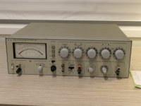
I've replaced the knobs and need to type up a chart what each position means. I also did some flattening out of the big dents in top and bottom. IMHO it looks a bit better, I do not mind having to consult a chart at all. Am already used to the frequency parts and oscillator level part, just the input level and the distortion require a bit of thinking. I just ignore the numbers on the settings where the switch does not go.
I will order some banana to BNC adapters while I am out of commision.
Thanks sofar, will be back.
The oscillator has some cr@p on it and although stable in frequency there is some lower frequency mixed in, around 30Hz by the looks of it.
Generating a signal with a computer should be fine, just need to find some software for it.
When the microwave went on (10 meters away) spikes and distortion galore, wondering if it is breaking through the mains.
I'll have to leave working on it for a while (lifted something today and have another collapsed vertebrae so back to bed rest for the next two to three weeks, that's osteoporsis for you). And other chores pile up in the meantime.
I've replaced the knobs and need to type up a chart what each position means. I also did some flattening out of the big dents in top and bottom. IMHO it looks a bit better, I do not mind having to consult a chart at all. Am already used to the frequency parts and oscillator level part, just the input level and the distortion require a bit of thinking. I just ignore the numbers on the settings where the switch does not go.
I will order some banana to BNC adapters while I am out of commision.
Thanks sofar, will be back.
Attachments
Last edited:
I suggest trying to make performance better in section 3-50 with filters off. I believe you're correct in suspecting hum or other relatively large interfering signal. Monitoring the Monitor output with your scope should give you insight about the nature of the problem. Internally, shielded cables connect A3 to the A2 board. Be suspicious of their integrity--- they might be culprits in hum or noise, especially since someone earlier has been wreaking havoc. You mentioned someone replaced input ground banana jack--- poor work there could be the problem.
A good a good divide-and-conquer test is to unplug cables at A2-J1, J2, J3 as appropriate and short the corresponding A2 input. Changes (or lack of) in meter reading should point the direction. The instrument must have low residual noise to achieve specified distortion performance. (Section 4-25 and earlier.)
If I measure distortion in Picoscope from the oscillator I get approx -55dB. If I measure distortion from the Picoscope AWG in the analyzer I get around -48 ~ -52dB.
If I measure the oscillator disortion in the analyzer I get around -24dB...

The power supply of the analyzer has been reworked, the 10uF capacitors replaced with 33uF and the 1000uF have also been replaced plus a new bridge rectifier. (by the previous hacker) There is about 7mV cr@p on the + & -15V, same as on the oscillator power supply which has not been touched.
Every charge pulse from the rectifier results in a spike followed by some ~ 5 Mhz and ~ 25 Mhz ripple for about 10 cycles. It also results in some fluctuation on the +15 and -15V DC.
Putting the oscilloscope on the oscillator TP3 and TP7 show the same cr@p coming through there. At low output signals I see that TP1 is rather clean but post buffer amp the same cr@p as on DC is coming through.
I have a suspicion that the incorrect 33uF capacitors or the replacement of the 1uF by 2.2uF in the analyzer power supply causes some instability. I'm going to bring it back to original design values - the designers knew what values worked best there.
Have ordered replacement capacitors for both power supplies and will see if the power supplies clean up and get stable.
Parts might take a week to 10 days to arrive.
Hi AM,
Your THD experiments are mysterious but I'll offer a few scattershot thoughts and suggestions.
I recommend using x10 scope probes--- x1 probes have enough shunt capacitance to provoke opamp oscillation when probing test points. If I must use x1 probes for the added sensitivity, I often clip a 220 ohm resistor to the scope probe hook and probe with the free end of the resistor--- the added resistance is usually enough to preclude oscillation.
I wonder if some of the rectifier hash you report might be instrumentation ground loop artifacts. An experiment: hook the probe's ground clip to the probe tip and note any displayed glitches that are internal to the scope; then touch the ground-scope-tip combo to the Monitor ground terminal on the analyzer and see if any additional glitches appear. Any additional glitch amplitude is likely to superimpose atop your probe measurements. It's conceivable that the glitches aren't enough to cause the problems you're seeing--- the 5MHz/ 25MHz ringing may not propagate down the analyzer's signal path which has about a 300kHz measurement BW. The hacked power supply might be OK.
I still believe the Monitor output may be the best initial insight to the problem. As a confidence builder, I suggest using your Picoscope generator as you've seen encouraging results re a THD measurement. Note the initial THD meter reading, then add the scope's ground clip to the to the Monitor ground binding post and look for any degradation in meter reading; next, add the scope's input to the monitor output and and look again for degradation--- hopefully none. Now looking at Monitor residual on the scope will give a preview of how distortion and noise present.
Since ground issues are under suspicion, I suggest leaving Pico generator in place and next adding connection of the 339A generator ground output post to the analyzer ground input post. Any degradation would suggest a grounding issue within the 339A. There's also the INPUT/GND SELECT slide switch to experiment with.
Finally, if the above experiments go smoothly, connect the analyzer's internal generator as the source and inspect the Monitor output. Poor residual THD should present as inadequate nulling of the fundamental, harmonic distortion content, hum, noise, or other spurious signals. I hope there will be some obvious defect to tackle.
Good luck!
Last edited:
Steve - thanks for the suggestions. I use a laptop and when doing measurements I disconnect from the mains and disconnect the internet cable - that cleans the signal up. At the moment not in a position to test these suggestions - still have to spend a lot of time on my back to help healing. But have to move every now and then to avoid musscle wasting.
Damian might be right that this is a basket case but I am not yet giving up. The rubbish on the power supply coming through may indeed be the result of some grounding, it may also be that an chip has been replaced and has a dry solder joint - too much scattershot work has been done to this 339A in the past so suspect the previous owner could not fix the probem.
I'll be eagerly waiting for the power supply caps to arrive, imho the voltage regulators are still OK, they would not both start behaving in the same manner at the same time. I may disconnect the oscillator form power and see what happens and there is a square rectifier bridge soldered on the other side of the PCB for the analyzer and I can disconnect one of the legs to the AC there and see what that has for result. One step at a time.
Later
Marinus
Both Steve and Demian are good at this stuff aren't they Marinus.
Marinus, from where did you purchase your 339A?
Also, you have the toggle on/off switch. I also have one 339A with a toggle
and one 339A with push button. My toggle switch 339A had an intermittent issue
and it affected both sides of my 339A, or the intermittent, would crop up and things
would go to scheisse pretty quickly.
RN Marsh took that one in and checked it out for me as I couldn't get it working properly
after I made a few too many "upgrades". Richard figured out what the main problem was
and kept the analyzer running for almost two weeks before the intermittent reared it's head again.
He had the correct gear to diagnose the problem and correct it.
He never told me what he did or what the fix was, other than he got it working
and said the better 339As were the push button on/off switchers.
Leads me to believe there is something in the switch, contacts, or wiring that
isn't quite right. That is what I know, though it might not be too helpful.
Next up I'm trying to find the original optocoupler data sheets, and the second
version of the optocoupler (tocopherol is what the spell check says the optocoupler should be)
that HP used after they couldn't get the first ones any
more.
Marinus, take some more pics of the 339A intermals when you get a chance please.
Cheers,
I use to annually calibrate the HP339A's, very nice units to use for measurements, the low noise OSC is a bonus.
The HP333A was more of a slow manual operation in using it and disliked it.
Managed to score a free clean working HP339A unit as everything is digital these days.
Will sit on my repair bench.
Cheers,
1 Pascal=94dB
The HP333A was more of a slow manual operation in using it and disliked it.
Managed to score a free clean working HP339A unit as everything is digital these days.
Will sit on my repair bench.
Cheers,
1 Pascal=94dB
The boatanchor has risen from the depths and is now aboard
Spend only a little time on it today.
You called it, almost <wink>! Performance improved.....
In the long thread the late davada remarked internal ground issues.
Soldered a ground lead from oscillator board to the analizer board and all came alive.
What I find mysterious is that only the +15V and - 15V go to the A2 board with a two pin plug. What about ground?
Aluminium chassis connections of equipment of this age will suffer galvanic action and current has to find another way. It is ideal to create a ground loop somewhere, often it goes through the shield of a signal cable. Oops, not good.
Further, on the schematic is a note that a ferrite bead has been added to pin 4 of both MC1496G demodulators to prevent 300Mhz parasitic oscillations.
Inspecting the board does not show these beads. Motorola spec sheet suggests to use a 1K resisitor in series for LF work but that it might degrade performance. I'm thinking of cutting the tracks close to pin 4 and soldering a 100 Ohm SMD there, it will help a lot and if there is any degradation it should be minor. (cannot see me succesfully removing the IC, or only pin 4, to put a bead on)
Anyway, it is working and need a good tune up. But I will first replace the capacitors in the power supply with the proper values and start tidying up. Front panel has to come off (not looking forward to that) and some posts replaced. I am also wondering if I should bring the output of the notch filter out to the AM BNC so I can hook up the Picoscope there and use it for FFT analysis as davada suggested. I want to float the BNC connector when doing this. Boatanchor? No more!
AM
...
Since ground issues are under suspicion, I suggest leaving Pico generator in place and next adding connection of the 339A generator ground output post to the analyzer ground input post. Any degradation would suggest a grounding issue within the 339A.
....
Spend only a little time on it today.
You called it, almost <wink>! Performance improved.....
In the long thread the late davada remarked internal ground issues.
Soldered a ground lead from oscillator board to the analizer board and all came alive.
What I find mysterious is that only the +15V and - 15V go to the A2 board with a two pin plug. What about ground?
Aluminium chassis connections of equipment of this age will suffer galvanic action and current has to find another way. It is ideal to create a ground loop somewhere, often it goes through the shield of a signal cable. Oops, not good.
Further, on the schematic is a note that a ferrite bead has been added to pin 4 of both MC1496G demodulators to prevent 300Mhz parasitic oscillations.
Inspecting the board does not show these beads. Motorola spec sheet suggests to use a 1K resisitor in series for LF work but that it might degrade performance. I'm thinking of cutting the tracks close to pin 4 and soldering a 100 Ohm SMD there, it will help a lot and if there is any degradation it should be minor. (cannot see me succesfully removing the IC, or only pin 4, to put a bead on)
Anyway, it is working and need a good tune up. But I will first replace the capacitors in the power supply with the proper values and start tidying up. Front panel has to come off (not looking forward to that) and some posts replaced. I am also wondering if I should bring the output of the notch filter out to the AM BNC so I can hook up the Picoscope there and use it for FFT analysis as davada suggested. I want to float the BNC connector when doing this. Boatanchor? No more!
AM
Last edited:
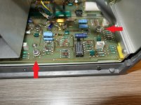
On the error detector assembly both demodulators (U2 and U4) appear to have been replaced (not the best soldering). They do not appear to be a Motorola MC1496G, the numbers do not make sense to me.
Do I need to replace this with genuine Motorola's while they are still available?
Do I need to replace this with genuine Motorola's while they are still available?
Attachments
- Home
- Design & Build
- Equipment & Tools
- Could use some help repairing my HP 339A