Could use some help fixing my HP 339A. Mark II.
It has been out of use for perhaps 18 mos. and it's obviously an old unit. When I fired it up anew, it mostly worked but was in sore need of switch cleaning, etc. After that most functions worked well: generator over its full range of frequency and amplitude, filters, voltmeter. Frequency response of amplitude and level tracking good. All switches now showed no intermittencies.
However, when it comes to THD that's another matter. To boil it down, when it is first turned on from cold (66° in the room overnight), the THD is about 50%. It starts to drift better over some minutes and get into the –14 dB range (which is the first bridge per the manual) and speeds up winding up about –50 dB. Then as it continues to warm up it reverses course and eventually comes back up to 50% (–6 dB of course). These are such long time constants I don't think they can be capacitor ones: possibly the heating of the onto-couplers?
My basic problem is how to break the problem down when there are multiple loops in the THD section. Is there someway to lock out part of it and get the main one nulling without all this drift? Can you imagine going down from –6 to –50? I can only do this once per day because it has to start cold so I'll be doing it over a few days as the first thing in the shop.
Has anybody else experienced long-term drift far above spec in this unit? So far I can't separately measure the oscillator, but I'm getting an AP soon and will be able to do that, but I don't suspect the oscillator or the metering, just the THD section and its multiple loops. Also at the moment I can't monitor the output on a scope (it's also being repaired) and when I connect a powered speaker to the monitor port it acts as though there's an open ground. That seems odd too.
Thanks in advance for any help you can provide.
It sounds to me like something is amiss in the notch circuitry. Get your monitor output working and look at the output with an FFT in THD mode. Most of that circuitry is on the plugin board at the rear of the emclosure. I found I had to replace the notch adjustment pots with 10-turn units to get stable THD behavior. For starters you might just pull that board, check the 'lytics, and clean the edge connectors really well.
My 339A is veery sensitive to ground noise on the units its measuring. Amps with switching supplies drive it nuts. At first I thought it was a fault; now I'm glad for it alerting me to the reality of dirty power supplies, bad grounding schemes, etc.
My 339A is veery sensitive to ground noise on the units its measuring. Amps with switching supplies drive it nuts. At first I thought it was a fault; now I'm glad for it alerting me to the reality of dirty power supplies, bad grounding schemes, etc.

On mine, at 1KHz thd 1V internal source (+600ohm load ) with 30K filter switched in suggests thd around -100dB down or pretty close to it. (pics). This is on all ranges and implies beating the factory specs by quite a margin. A quirk...don´t use a digital scope as a monitor. They are quite noisy, which breaks through into the 339A monitor circuitry. Use an analogue scope.Hmmm, that's interesting, thanks. The 339A freq decade switches have single resistors for the bottom 5, and parallels a second set across them for the upper 5, which would lower inductive strays. Surprising it makes that much difference.
Would still be interested to hear whether folks use the 10X 100 or 1X 1k combo when optimizing the 1kHz distortion.
However, I have with a problem when the internal oscillator is used as the distortion source signal and the frequency vernier is set to CAL. Immediately the left LED announciator of the frequency scale illuminates, and moving the LHS knob frequency to one increment to lower frequency, OR rotating the frequency vernier mid way round, extinguishes that announciator LED but it tells me the notch/freq alignment is "not down the line" with frequency. Rather strange that illustrating such a low thd performance suggests there is absolutely nothing amiss.
Anyone else also notice this issue ?
Indeed, maybe I should be satisfied enough that there are no other problems.
Varying the presets on A4 board doesn´t solve the issue. The issue seems to stem from the error detect board where R43 & R16 interact, are already optimized for min thd.
By the way, before moving presets on any board make sure to mark the original positions with a fine felt tip !!
rj
I'm suspicious of the whole "phase control" part of the circuit, which narrows the notch. A DC "phase error" signal from the A4 board controls a photoresistor, which is in series with some "phase control" resistors that get switched along with the MSD of the freq selector, and are in parallel with the C's of the twin-T. Those R's are present for numbers 1-5 but bypassed (shorted out) for 6-10. Maybe a symptom of an aging photoresistor? I bet the "level pumping" at some freq settings is concurrent with the error signal DC swinging wildly.
This would be an interesting learning exercise to suss out... maybe another time. For now, I can work around it.
Attachments
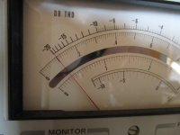
On mine, at 1KHz thd 1V internal source (+600ohm load ) with 30K filter switched in suggests thd around -100dB down or pretty close to it. (pics). This is on all ranges and implies beating the factory specs by quite a margin.
That's good for a basically stock unit. You can lower it another 6-8dB by applying the various mods outlined in the 339A threads on this forum.
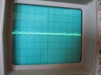
Not all of them are bad. That's caused by ground noise currents from the DSO's smps. If the THD+N goes up when you connect the DSO to the monitor out, you can't use it, try another one. Or isolate it with a low-distortion transformer, such as those in the HP 353A patch panel. A DSO with FFT on the monitor out is very useful. BTW, some DUT's with smps will do the same thing.A quirk...don´t use a digital scope as a monitor. They are quite noisy, which breaks through into the 339A monitor circuitry. Use an analogue scope.
Well, true having spent an afternoon on debugging, I could replace some early generation IC´s as they have improved, but I´m quite content when the needle is already at the near-end of the scale. What does make a difference is turning on the 339A a good 20 mins beforehand. That´s a sure indication of IC´s stabilizing down.
Surprisingly my (pricy) digital TeK TDS2022 does contribute a fair amount of noise be it ground injected. My old analogue 2245A (wonderful 1980´s scope) solved the noise issue.
I found that little problem regarding those two LED´s on the frequency scaling was down to the rear error detector board variant that missed the HP mods; the comparator levels are way out. Trick is to remove R59-R60 and solder a 500R present in-lieu with the wiper going to pin 12 of the comparator. It solved the issue but I will double check functionality.
Also somewhat unrelated faultwise, that HP in those early years used a dreadful 650uf electolytic (C25) across U5B which was reading low C; solution is replace with a today´s generation 680uF.
As other users remarked, at 10 Hz the analyser on THD setting takes some time to settle but who uses it at this low frequency ?
More anon as always.
rj
I found that little problem regarding those two LED´s on the frequency scaling was down to the rear error detector board variant that missed the HP mods; the comparator levels are way out. Trick is to remove R59-R60 and solder a 500R present in-lieu with the wiper going to pin 12 of the comparator. It solved the issue but I will double check functionality.
Good catch. I also have an older unit, but don't have that issue.
Also somewhat unrelated faultwise, that HP in those early years used a dreadful 650uf electolytic (C25) across U5B which was reading low C; solution is replace with a today´s generation 680uF.
Thanks for pointing this out. When I upgraded/refurbed mine a couple years ago, I checked that cap for value but not for leakage. It could well be causing the issue mine has.
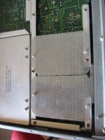
That area around C25 on my board and those resistors R59 etc (worst place at the rear circled in yellow) seems to have gone through a 1980 annum board botch-up with tracks re-glued, so either an incompatible non-modified board was fitted or more like swapped, but either way there was a previous problem as many tracks were missing. The only way of working on this board is pulling it out of the main socket or tacking long wires.
There is also another strange issue with distortion; select 100Hz frequency, but take note which frequency selectors to get this frequency. I get a slightly different thd and (better) result by selecting 10Hz then x10 multiplier rather than selecting straight 100Hz. With internal ground selector on, I put this down to the slightly increased wafer switch and board wiring around the high impedance oscillator, somewhat undesirable. We are nit-picking dust around -95dB down but I didn´t let this go unnoticed. I suppose the oscillator section could have done with PCB under track metal screening with a local earth rather than the unit base.
Now I shall do a fresh specification of the unit and see how it differs.
rj
Attachments
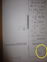
That area around C25 on my board and those resistors R59 etc (worst place at the rear circled in yellow) seems to have gone through a 1980 annum board botch-up with tracks re-glued, so either an incompatible non-modified board was fitted or more like swapped, but either way there was a previous problem as many tracks were missing.
Mine as well. Wire-wrap wire replacing damaged traces. It seems things weren't settled in the design and early boards went through revisions before going into the field. Even HP techs had some difficulty removing parts without trace damage.
Turns out R59/R60 on mine were neither the "original" values (200 & 200) or the "recommended" ones (301 & 100), but 356 and 44. I installed the 301 & 100 and it works except sometimes it latches up when the hi-level indicator is lit. The only way to release it is powering down, giving a few seconds for caps to discharge, and then power up. I'll put the originals back in.
I pulled C25 and checked it. 650-ish uF value was ok, DF fairly high even at 100Hz, and leakage was better than the spec calls for; less than 600nA at 9V in 2 minutes. I think those caps are "wet tantalum" types. HP used them in many instruments where high-uF at low volts was required. I checked several others in my parts bin and they all have very low leakage.
Turns out that leakage spec is not easy for a modern 680uF 16V or better 'lytic of similar size to meet. Most of them never got below 1uA; a couple took 5+ minutes. I finally found a Nichicon UHE 680u @ 25V that just made it. Installed in-circuit, I don't see any difference.
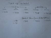
There is also another strange issue with distortion; select 100Hz frequency, but take note which frequency selectors to get this frequency. I get a slightly different thd and (better) result by selecting 10Hz then x10 multiplier rather than selecting straight 100Hz.
Yes, mine is the same, and others have noticed this as well. 10Hz x 10 is 5-6dB less THD than 100Hz x1. Same at 1kHz. I can live with it.
I found a better copy of the manual changes (yes jbau thanks!); as mine was very blurred, even worse with the illegible parts list; but lo behold, historically, the values of error board A4 R59 & Co went though many series changes.Mine as well. Wire-wrap wire replacing damaged traces. It seems things weren't settled in the design and early boards went through revisions before going into the field. Even HP techs had some difficulty removing parts without trace damage.
Turns out R59/R60 on mine were neither the "original" values (200 & 200) or the "recommended" ones (301 & 100), but 356 and 44. I installed the 301 & 100 and it works except sometimes it latches up when the hi-level indicator is lit. The only way to release it is powering down, giving a few seconds for caps to discharge, and then power up. I'll put the originals back in.
I pulled C25 and checked it. 650-ish uF value was ok, DF fairly high even at 100Hz, and leakage was better than the spec calls for; less than 600nA at 9V in 2 minutes. I think those caps are "wet tantalum" types. HP used them in many instruments where high-uF at low volts was required. I checked several others in my parts bin and they all have very low leakage.
Turns out that leakage spec is not easy for a modern 680uF 16V or better 'lytic of similar size to meet. Most of them never got below 1uA; a couple took 5+ minutes. I finally found a Nichicon UHE 680u @ 25V that just made it. Installed in-circuit, I don't see any difference.
Yes, mine is the same, and others have noticed this as well. 10Hz x 10 is 5-6dB less THD than 100Hz x1. Same at 1kHz. I can live with it.
After measuring the near optimum operation values with a 500R preset in lieu, I arrive close to the suggested values for that instrument build series, of 300R & 68R. My change isn´t optimum but this LED function isn´t a calibrated one. So be content!
As for the 650uF cap (C25) yes the original is a wet tant type but the Nichi replacement which does have a low leakage current, would appear not the ideal replacement but it got me going. I measured the volts across this cap on both lock-in/out ranges and it swings from a few mV to 8.6V with lock range in between. I shall search for a very low leakage type, as manual suggests a near impossible figure of 0.6uA ( beyond the region that most vendors stock) no doubt may have to be made up. How awkward and worse in cramped space.
Is this low leakage requirement necessary and the circuit dissection goes further. Examining the circuit around U5B on A4 board I am surprised to such a low loss cap requirement as the neg side of this 650uF (C25) cap is connected to16K2 resistor (R49) to a near zero o/p amp source of U5A. The zener diodes CR13/14/11 all have combined reverse currents greater than the 650uF. So why the tough requirement ? Putting this in perspective, all agree or not ?
My next move is the negative voltage regulator U301 which is a dual pos and neg type for both oscillator and meter circuits. I presume this is an HP special as none of the circuit correlates to any discrete data in my collection. As it has a boost capability, could it be a LM304/723 in one package ? There appears to be NO voltage adjustment on either. A tip on this would be welcome.
rJ
manual changes
I found a cunning way: I charged the cap on test to 10 V with it having 10V charge, then connect a Fluke multimeter on Volts selector (which nearly all have a 10Meg input resistance) in series with the cap back on a 10 V supply and watch for a steady settling reading. The leakage current then can be worked out with Ohms law.How are you measuring cap leakage? Its not easy when looking at such low leakage parts.
The "wet tantalum I pulled out immediately looses it´s charge (as multimeter volts rose quite quickly) where as a relatively new Rubicon ally cap of the same value held charge up overnight. I did this test with several and soon found the leakage value way below what is required. Replacing the 650uF with a 1000uF 25V steadies the meter better around the -95dB point at 100Hz but having spent much time trying to debug that strange synchronized warbling around that frequency setting on the -80dB distortion range, I suspected a stray mag field from the small mains transformer, but it wasn´t the culprit.
The oscillator on the HP339A is mighty sensitive to strays around the wafer selector wirings, so I fitted an extra screen above the wafers quite high up which helped, but it was not the solution to the problem. Even with selecting the input selector switch toe chassis earth, I then tried mounting a screen on the solder side of the oscillator pcb, and that made things worse.
Having been in my youth an RF engineer, it immediately ocurred or gave the hint that the fet oscillator is in fact not quite so frequency stable as one is led to believe. The slightest spurious in the ground plane i.e miniscule 100Hz ripple on the pcb can set other phase interactions in motion with the already sensitive deep notch filter.
We are already at -95dB down so with other frequency settings it behaves fine. I am going to fit the 1000uF cap instead of the 680uF and leave it at that.
On the circuit diagram relating that the problem area around that 650uF cap, I also found R66 had a 13K fitted instead of a 15K. There appears to be quite a few inconsistent modifications. A spare board had different values fitted. HP esp. R&D must have had quite a few problem issues over optimizing the component values of this section.
rJ
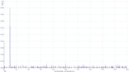
Regarding the oscillator on the 339A; I found it pretty clean when output taken directly from socket. see pic. Ignoring the fractional log scale, (an awkward feature of the picoscope software), the evidence shows. There are other mods I did, screening the underside of the oscillator reduced chassis noise even though there is a slight frequency shift. I am surprised HP didn´t do this screening measure, as the otherside is well screened.
A sideways tip; the monitor output really does mean it, NOT for instrumentation readings. There is alot of digital and phase noise on this terminal. The noise spectrum is appalling.
A sideways tip; the monitor output really does mean it, NOT for instrumentation readings. There is alot of digital and phase noise on this terminal. The noise spectrum is appalling.
Attachments
Yes, mine is the same, and others have noticed this as well. 10Hz x 10 is 5-6dB less THD than 100Hz x1. Same at 1kHz. I can live with it.
Breakthtough on mine:- At -95dB down is pretty low level and will pick up minuscule circulating ground loop currents around the chassis when the monitor output and inputs are connected to other equipment:-which are also earthed. Another important issue is make sure all chassis screws are tight and complete.
HP339A Power section: I replaced the existing chassis IEC mains socket/filter with a version that had no XY caps nor filter inductors, and wired the AC appropriately; but with the earth I abandoned the 40uH choke and simply strapped two high current silicon diodes in parallel A/C, C/A so that the chassis can float 0.7V thereof to avoid ground circulating currents. The important thing here is those diodes must be rated appropriately. I used 8A slow types. Now the meter is much steadier. Another point to bear that in 1977 the 339A was good for it´s time as the audio equipment standards barely hit -90dB down even on studio equipment, until later when the Neutrik THD analysers mastered this down to -100dB.
Still curious, on the circuit schematics regarding the power supplies, one for the oscillator and other meter both have a "0" rail. Question is where are they joined ???
rJ
By chance I had a spare back board; the orig. Rev B (pic) changed to the Rev C version and that solved all the instrumental evils. IC wise´ there is no point changing anything else to get a better performance as I now get noise -95dB down at 50Khz using 80Khz filter, and at lower frequencies nearly -100dB down. Turning off the filters the only fine grass noise is from the demodulator ICs. Examining the board differences there appears only some resistor changes but one must confess the layout is abysmal. Was it worth the gold plated ? The name perhaps yes, but elsewise the modification history was a shambles.Yes, mine is the same, and others have noticed this as well. 10Hz x 10 is 5-6dB less THD than 100Hz x1. Same at 1kHz. I can live with it.
BB
Attachments
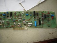
Examining the board differences there appears only some resistor changes but one must confess the layout is abysmal. Was it worth the gold plated ? The name perhaps yes, but elsewise the modification history was a shambles.
I'm curious if the component changes you noticed between the two board versions agrees with the revision changes detailed in the manual.
Jbau... The main resistor changes appear to be the area around LED announciators aka U6 comparators (high and low + level /freq) on the A4 rear board. I examined this board and as mentioned was not impressed with the +/- 0 volt returns and decoupling all which are very long. My C version did not have a ferrite bead on U whereas the B version has one fitted, so I put a small 3e25 bead on it. For whatever reason this C version board is quieter than the B version and yet the ic´s are identical. I very much doubt any more improvement going to even lower noise op amps with the current lanky layout.
There is also another mystery I have yet to find, and that is the selectable front panel earth switch on the drawings- On my schematics it is nowhere to be seen. Quite possible I am missing a page. The other general mods, is I put an separate perforated screen under the oscillator area (which is quite sensitive) earthed to the local board earth in that area. Originally the equipment covers behave as a general screen but with such long earths and each cover having only one screw at the rear, this is not good practise from a noise point of view.
Now some measurements; I get (80Khz filter in) thd wise at 10Khz obtainable -95dB down;. 5Khz -100dB down; 1Khz and below ditto. All this is well in spec.
This is as far as I go hunting with modifications other than the obvious such as PSU cap replacement. Still, as it stands this 1975 piece of virtuoso analog equipment, the HP339A still commands quite a high price, probably more influenced by the gold pcb plating than the rest of the innards. The next generation analysers do not have to resort to gold plating and use high-end sound cards with all the op amp refinements with digital interfacing. The latter generation Neutrik types using programmable inputs could get thd and noise down to -120dB.
BB
BB
- Home
- Design & Build
- Equipment & Tools
- Could use some help repairing my HP 339A