I have had this VTVM for 15 years in impeccable service. The only care it has received so far was both valves replaced when I bought it as defective and regular calibration against the DMM. Since this unit was made in the 50s, I thought I should refresh it. I got the schematics and opened it to check it. Being a measuring equipment, I wasn't impressed by the precision of components inside. Beside the carbon composite resistors, there are the following capacitor types: "dry electrolytic" (probably tantalum), paper and ceramic (both used on signal path) and Micamold. The latter's value marks do not correspond to the schematics. Papers and ceramics are 10%, others are 20% tolerance. This is probably what was available to the industry back then.
Beside cleaning the rotary switch contacts and checking the solder joints, I was thinking about replacing the capacitors with tighter tolerances and newer types, as particularly old papers and micamolds are surely out of spec and leaking.
What would you recommend as replacements for the original types, namely:
- signal paper
- signal ceramic
- micamold
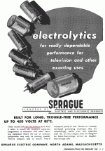
- dry electrolite
Thank you in advance for your opinions.
They are certainly not tantalum. (This is just old enough that users remembered "wet electrolytic", a technology which faded from radio-work by the 1940s.)
The meter movement must be pretty good. The rest of it is under heavy NFB and very stable against drift. Power caps could be 40, or 33, or 50uFd, no real difference. Yes, check C8 C13 for leakage-- in fact Heath gave good DC voltages which will point to any extreme drift.
The meter movement must be pretty good. The rest of it is under heavy NFB and very stable against drift. Power caps could be 40, or 33, or 50uFd, no real difference. Yes, check C8 C13 for leakage-- in fact Heath gave good DC voltages which will point to any extreme drift.
... capacitor types: "dry electrolytic" (probably tantalum)....
Attachments
Probably a capacitor became microphonic.
I think you mean loudspeakeric
Best regards!
I recently checked my 50 year old VTVM Heath Kit IM-18.
I couldn't DC zero balance the front end. A quick ohms check on several carbon comp. resistors were found way out of tolerance > 10%. Also one of the Cal potentiometers had to be replaced due to collateral damage from a leaked C cell. Further checks found the high voltage AC paper cap to be leaky, so was replaced with a modern film type. I didn't replace the original electrolytic cap because I didn't detect any other anomalies calibrating the meter. I believe only other ( 2 ?) caps were ceramic disk types and were never suspect esp. after the meter was balanced. I wouldn't sweat tightening the tolerances of any other components, no improvements on the poor specs of any VTVM meter movement even when compared to the cheapest DMMs. The best thing to hope for is getting accurate \\ results is do the final DC cal on a single range of your choice.
Following modifications were implemented. I replaced the probes phone jack with a BNC panel jack. also moved the custom probes 1M series resistor inside the meter to one of the original wafer switches. I measured the input impedance both on DC and AC and was satisfied the mod. was working. note this isn't ideal on AC loading depending on the actual coax cable on a new probe assembly.
Last edited:
- Status
- This old topic is closed. If you want to reopen this topic, contact a moderator using the "Report Post" button.
- Home
- Design & Build
- Equipment & Tools
- Heathkit IM-21 refurbishing
