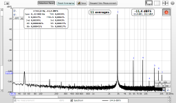
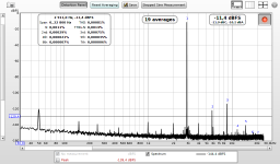
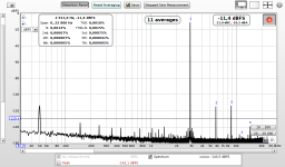
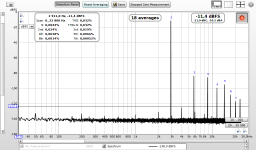
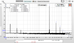
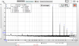
The other "well behaving" 4556 nb. 4:
1) 1x yesterday - 0.00067%
2) 1x - 0.00060%
3) 11x - 0.0059% => 10x
4) 48x - 0.029% => 48x
Also notice how similar the individual harmonics on the 1x screenshots are.
1) 1x yesterday - 0.00067%
2) 1x - 0.00060%
3) 11x - 0.0059% => 10x
4) 48x - 0.029% => 48x
Also notice how similar the individual harmonics on the 1x screenshots are.
Attachments


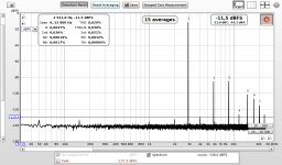
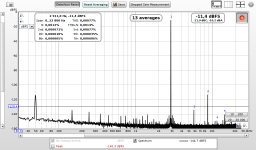
Now 4556 nb. 2. This appears like it has the common-mode distortion somewhere around 0.00015% and the remaining distortions being majority of the distortion profile. I do not know.
1) 1x - 0.0019%
2) 11x - 0.0029% = 11x 0.00015% + 0.0012%
3) 48x - 0.0085% = 48x 0.00015% + 0.0012%
1) 1x - 0.0019%
2) 11x - 0.0029% = 11x 0.00015% + 0.0012%
3) 48x - 0.0085% = 48x 0.00015% + 0.0012%
Attachments


Last edited:
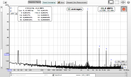
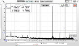
The remaining 4556 nb. 3 behaves differently. Measurements are identical from yesterday.
1) 1x - 0.0010%
2) 11x - 0.0019%
3) 48x - 0.0098%
The 5532 displays a similar pattern - nonlinear increase in distortion
4) 1x yesterday - 0.00075%
5) 1x - 0.00077%
6) 11x - 0.00081%
7) 48x - 0.00130%
1) 1x - 0.0010%
2) 11x - 0.0019%
3) 48x - 0.0098%
The 5532 displays a similar pattern - nonlinear increase in distortion
4) 1x yesterday - 0.00075%
5) 1x - 0.00077%
6) 11x - 0.00081%
7) 48x - 0.00130%
Attachments
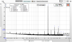

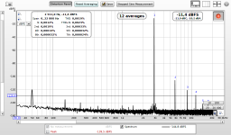
One thing I have noticed. The two "well-behaving" 4556s (1, 4) have a clearly higher noise floor at 48x than the two "non-behaving" 4556s (2, 3).
Also their overall distortion at 1x gain is much lower, but is attributed almost completely to common-mode type. The other two start at higher distortion which grows much slower and at 48x ends up way lower.
They behave a bit like two different chip groups. But 1, 3, 4 are labeled JRC and look the same, 2 is some generic RC4556.
If I were to measure all 4 opamps with the high-gain method, I would pick 2 (0.0085%) and 3 (0.0098%) as opposed to 1 (0.032%) and 4(0.029%). Yet in no-gain scenario the winners are the other way round 1, 3 (both around 0.00060% ) vs. 2 (0.0019%) and 3 (0.0010%).
Attachments

Last edited:
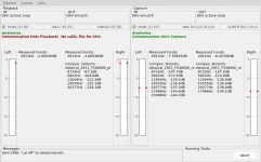
During measurements the tool has compensated distortions on both sides. The right channel on capture side was used for measurements, the left channel keeps receiving full output signal to preserve the same conditions as during the calibration.
After swapping each opamp the recording side was quickly recalibrated to make sure all opamps get the same conditions. Since all opamps had same output level, no multiturn-pot adjustments were required, calibration was just a matter of flipping the in/out switches and selecting the "Calibrate capture side" in menu - 4 seconds in total. The playback side was split-calibrated only at the beginning of today's measurement session.
After swapping each opamp the recording side was quickly recalibrated to make sure all opamps get the same conditions. Since all opamps had same output level, no multiturn-pot adjustments were required, calibration was just a matter of flipping the in/out switches and selecting the "Calibrate capture side" in menu - 4 seconds in total. The playback side was split-calibrated only at the beginning of today's measurement session.
Attachments
Last edited:
My 2 cents the opamp nb. 3 labeled JRC 4556 yet displaying very similar characteristics to the nb. 2 labeled RC4556 is a fake, relabeled chinese RC4556 as brand JRC.
The RC5534 is vintage Raytheon from the time that they (Raytheon) had their own selection and branding specs for vendors. They are screened for MilSpecs. I have a few RC5534's and they are definitely no fakes.
But your findings are very intriguing, I have no suggestions to offer, unfortunately.
Jan
Attachments
Last edited:
They all may be chinese fakes. I bought them locally a few years ago (probably in several batches) but small local sellers carry chinese production too.
The three "JRCs" look like this one with faint print WORKING GENUINE JRC 4556D OPAMP OP AMP - 70MA INTO 150OHM AT 10V - UK SELLER | eBay
But they could easily be [ SA ] | NJM4556AD NJM4556 JRC4556 lower noise dual op high slope with low distortion 10PCS/LOT-in Integrated Circuits from Electronic Components & Supplies on Aliexpress.com | Alibaba Group
The RC4556 print is larger and more visible, like 5 Stuck - RC4559NB RAYTHEON - Dual High Performace OpAmp DIP8 VINTAGE - 5 pcs | eBay
IMO the two "well behaving" come from the same batch while the other two have been produced from a different matrix/substrate, very likely two batches with similar type of layout. But definitely different internals/parameters than the "well behaving" ones.
The result for me is the high-gain measured THD cannot be linearly extrapolated down to single-gain values safely. Measuring at single gain yields very different THD for presumably same chips.
Since measurements of the two "well behaving" show almost linear scaling in distortion-gain method (10% error max) and single-gain measurements a day apart yield basically same figures, I have found no indication that the distortion compensation method provides incorrect data.
Calibrated E-MU closed loop has THD below 0.00002%. Capture-side calibrated at voltage divider yields 0.000013%, upon switching to LPF at the same level 0.000020% (LPF rotates residual distortions from the compensated playback side). That gives a resolution headroom of 30x for the least distorting opamp measured (0.000600%).
Last edited:
But how do we know how an original should measure, at single-gain? I did not find it in any of the various 4556 datasheets available.
I guess a notch filter + fine amplification should give credible results, to compare with the compensated distortions method.
Actually in this case I do not worry about fakes, the two "behaving good" show decent THD, be they fake or not")
One of the "non-behaving" had slightly lower output at all measurements (by about 0.02dB), I fine-tuned the pot when calibrating the capture side. The other four opamps had same level to 0.001dB (-8.443dB). Very minuscule country indeed
A few other findings. E-MU input level travels a bit when the input gain is not at 0dB endstop (where the slider probably touches the terminal directly, without any resistive path in between). At endstop, the level flips at 1e-5 dB digit. Slide into the resistive path, and the level starts drifting, at 1e-3 dB in about a minute. It looks as if the current through the path warms up the resistive element a bit and changes its params. Not a big deal, but for precise measurements it may require more frequent capture-side calibration, or range calibration at some interval around for the interpolation to kick in.
On the other hand the input amplifier in E-MU is very convenient since it is part of the capture-side compensation block, making its distortion compensated. All these measurements are single-ended which means -6dB max signal to start with - a minor amplification would not hurt. I have seen the E-MU mod replacing the single-turn pot with the same 10-turn wired pots I use for calibration, probably quite useful mod. But I would definitely wrap the plastic pot with grounded copper tape, the effect was visible on the spectrum of the calibration adapter.
The LPF takes a while to "warm up" to keep stable output level too. Switching the calib adapter to the multiturn pot - the level is rock solid with 1e-5dB digit flipping. Switching to the LPF - the level slowly changes (1e-4dB digit, about an order of magnitude slower than the E-MU input change off endstop). After a few minutes the level settles down. I want to try keeping the LPF connected to the output (i.e. "powered on") all the time, it should not affect the output (10k resistor + C).
I guess a notch filter + fine amplification should give credible results, to compare with the compensated distortions method.
Actually in this case I do not worry about fakes, the two "behaving good" show decent THD, be they fake or not
One of the "non-behaving" had slightly lower output at all measurements (by about 0.02dB), I fine-tuned the pot when calibrating the capture side. The other four opamps had same level to 0.001dB (-8.443dB). Very minuscule country indeed
A few other findings. E-MU input level travels a bit when the input gain is not at 0dB endstop (where the slider probably touches the terminal directly, without any resistive path in between). At endstop, the level flips at 1e-5 dB digit. Slide into the resistive path, and the level starts drifting, at 1e-3 dB in about a minute. It looks as if the current through the path warms up the resistive element a bit and changes its params. Not a big deal, but for precise measurements it may require more frequent capture-side calibration, or range calibration at some interval around for the interpolation to kick in.
On the other hand the input amplifier in E-MU is very convenient since it is part of the capture-side compensation block, making its distortion compensated. All these measurements are single-ended which means -6dB max signal to start with - a minor amplification would not hurt. I have seen the E-MU mod replacing the single-turn pot with the same 10-turn wired pots I use for calibration, probably quite useful mod. But I would definitely wrap the plastic pot with grounded copper tape, the effect was visible on the spectrum of the calibration adapter.
The LPF takes a while to "warm up" to keep stable output level too. Switching the calib adapter to the multiturn pot - the level is rock solid with 1e-5dB digit flipping. Switching to the LPF - the level slowly changes (1e-4dB digit, about an order of magnitude slower than the E-MU input change off endstop). After a few minutes the level settles down. I want to try keeping the LPF connected to the output (i.e. "powered on") all the time, it should not affect the output (10k resistor + C).
Last edited:
I have been asked about support for RTX6001. It is presumably a standard XMOS-based USB audio device, good decision to avoid coding and maintaining drivers. If it has no vendor-specific quirks, it should work in linux out of the box. I am really looking forward to seeing compensated measurements from this low-noise/low-distortion device.
The other competitor QA4xx is unfortunately windows only, no linux drivers available. Maybe when the asio open source drivers exist now, the next step could be...
I will fix a few things in the tool which popped up during the opamp measurements, and then prepare the linux mint image for download.
The other competitor QA4xx is unfortunately windows only, no linux drivers available. Maybe when the asio open source drivers exist now, the next step could be...
I will fix a few things in the tool which popped up during the opamp measurements, and then prepare the linux mint image for download.
I have both qa401 and RTX. The RTX is fully compatible with Linux and when I get some time I will explore this work. Getting it setup in Win 10 would be great simply because the software options are greater.
Maybe Jens can figure out how to incorporate it into the driver so it's done in the XMOS interface.
I can also check with many different opamps etc. Not to mention analyzers. If anyone near me has a student to sacrifice this could happen much faster.
In all the systems I have tested keeping the level at -15 dBFS gives the best distortion results at a cost in SNR. Also, when dealing with such low distortion levels, using dB instead of % really helps reduce confusion. Counting zeros is tedious and error prone. . .
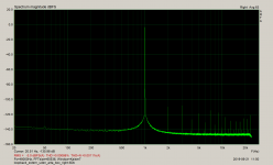
Like this :
These are harmonics. I do not like the forest all the way up to fs/2, but THD as well as THD+N are still within specs of that device. Try to lower the level, this looks like first signs of approaching limitation.
Your E-MU has input amplifier, use it to find out whether it is the DAC or ADC side which starts limiting.
The joint-sides compensation will clear these harmonics but 20th+ harmonics of 1kHz are very attenuated in the LP filter, lowering the split-sides precision so far from the fundament. Also measuring the LPF&VD transfer all the way to 20th harmonic takes some time.
But my 2 cents if you lower the level the high-order harmonics will drop significantly.
Getting it setup in Win 10 would be great simply because the software options are greater.
The jackd loopback https://www.diyaudio.com/forums/equ...nsation-measurement-setup-19.html#post5790925 works OK, it just takes a few extra steps to setup and the softwares involved must be started in specific order for all the devices to show up correctly (unlike in linux where the alsa loopback is a system sound device). Not good for regular operation, but feasible for testing the concept. The compensation tool runs in windows OK, playrec compilation for ASIO is described in detail on my wiki.
Maybe Jens can figure out how to incorporate it into the driver so it's done in the XMOS interface.
Please what is the problem specifically? Is the device operated by some side USB channel, or by vendor-specific controls within the USB-audio class
2 protocol?
Also, when dealing with such low distortion levels, using dB instead of % really helps reduce confusion.
The compensation tool UI uses dBs. I found the corresponding checkbox in REW setup, did not know about the option, thanks.
The jackd loopback https://www.diyaudio.com/forums/equ...nsation-measurement-setup-19.html#post5790925
Please what is the problem specifically? Is the device operated by some side USB channel, or by vendor-specific controls within the USB-audio class
2 protocol?
I was suggesting that the XMOS USB interface chip has enough processing power to implement the DSP compensation so nothing is required at the host PC. Obviously there are issues of enabling etc. but it would be a really interesting feature.
I want to keep my cards open. I am a fan of open source software, my software implementation of the project is open source GPL v.3, anyone can create a new open source implementation (java would make sense). Anyone can use the existing tool with any audio device, anyone can build this technology into open source measurement software should they wish.
But I am currently looking at options to have a way to license the technology to commercial closed-source/embedded products. I do not know if there will be any interest, but I want to try. That is a fair deal, in my opinion.
But I am currently looking at options to have a way to license the technology to commercial closed-source/embedded products. I do not know if there will be any interest, but I want to try. That is a fair deal, in my opinion.
Last edited:
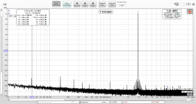
The E-MU 0404 input amplifier is not really usable for this purpose. Its level fluctuates (not caused by the potentiometer) and even constantly running joint-sides calibration does not work properly, the first two harmonics are cleared only up to 130dB.
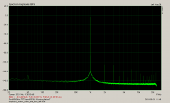
But with pot at 0dB the level is solid and the performance is not bad. This is split-sides calibration at max. level provided by the SE setup (hot lines of the balanced outputs/inputs), 1M FFT with the latest beta REW. Great work done on REW, thanks John for this great tool!
But with pot at 0dB the level is solid and the performance is not bad. This is split-sides calibration at max. level provided by the SE setup (hot lines of the balanced outputs/inputs), 1M FFT with the latest beta REW. Great work done on REW, thanks John for this great tool!
Attachments

Last edited:
The jackd loopback https://www.diyaudio.com/forums/equ...nsation-measurement-setup-19.html#post5790925 works OK, it just takes a few extra steps to setup and the softwares involved must be started in specific order for all the devices to show up correctly (unlike in linux where the alsa loopback is a system sound device). Not good for regular operation, but feasible for testing the concept. The compensation tool runs in windows OK, playrec compilation for ASIO is described in detail on my wiki.
Please what is the problem specifically? Is the device operated by some side USB channel, or by vendor-specific controls within the USB-audio class
2 protocol?
The compensation tool UI uses dBs. I found the corresponding checkbox in REW setup, did not know about the option, thanks.
I haven’t turned mine on in a while but I think there is a separate HID descriptor /endpoint that Jens uses to send his device specific configuration data.
- Home
- Design & Build
- Equipment & Tools
- Digital Distortion Compensation for Measurement Setup