I hope that the phofman's method does not try to eliminate/cancel any harmonic frequencies it finds.
I would have thought the method had been explained thoroughly in detail a few times here.
The compensation does not look for any harmonics. It keeps compensating the harmonics (adjusted for current fundamental amplitude and phase) measured during the calibration phase.
Several times have I shown a spectrum where artificially added distortions on playback side were properly identified. Yesterday I tried -130dB for 2nd and -130dB for 4th, Arta measured -135dB for 2nd and -130dB for 4th, while the signal went through a voltage divider of -1.6dB and the input stage has -0.3dB attenuation compared to the output. That means the distortions of -130dBFS on output were actually -132dBFS on input.
Last edited:
The ability to drag a WAV file onto the RTA window for processing was added in REW V5.20 beta 6.which might be REW as well once it has an offline feature added, in order to use the analyzer on files -- 64bit floats --rather than on the 24bit input stream
As of files - the tool supports playback and recording of audio files on any side. This gives many new options:
* A spectrum analyser without file support (e.g. Arta, jaaa) can read from the tool loopback "soundcard", while the file is being played by the tool.
* An audio file can be recorded in loopback on one machine, copied over to a machine running the tool (no soundcard required), and a distortion-compensated (joint-sides only) version can be stored by the tool for cleaner playback on the original machine.
* A testing signal produced by some analyser can be bit-perfectly recorded by the playback side.
* DUT output signal can be recorded at any time, while being displayed in the analyser
* etc.
Last edited:
Since the noise gain resistor also magnifies offset, you might want to put a large capacitor in series with it to prevent that from happening at DC. This may help the harmonic profile match if the offset is significant enough to change the crossover point of the output stage. it is of course only valid above the crossover frequency of the noise gain resistor and the capacitor.
I would not expect an electrolytic cap to cause error in this position since the AC across it is extremely small, and it's distortion only applies to the error signal, not the full fundamental voltage swing.
Everything about the circuit should be the same except for the addition of the noise gain resistor and cap, if what you want is a valid comparison. So there is no need to change the load resistor.
Excellent, I didn't know this was possible. Thanks!The ability to drag a WAV file onto the RTA window for processing was added in REW V5.20 beta 6.
Seems I've found a small bug, will report in the official REW forum, plus a request for 64 raw double input data.
For more details on the distortion gain method, Samuel Groner used it to test several opamps:
http://www.nanovolt.ch/resources/ic_opamps/pdf/opamp_distortion.pdf
http://www.nanovolt.ch/resources/ic_opamps/pdf/opamp_distortion.pdf
Thanks a lot, very interesting.
We have been talking about the circuit for amplifying/measuring common-mode distortion (Fig. 2.1b, attached). But the distortion measured by the compensated loop for plain non-inverting circuit is the sum of all the distortion types discussed in the paper. Therefore, a direct multiple will not hold.
Nevertheless, I will be happy if the precision is within correct order of magnitude")
I have to rework my calibration adapter first, to shield the multiturn pot properly and to improve overall shielding and signal separation.
Also, I can compare opamp results measured with the existing PCI soundcard and E-MU 0404 USB https://www.diyaudio.com/forums/equ...04-linux-issues-rew-96-khz-2.html#post5819899
We have been talking about the circuit for amplifying/measuring common-mode distortion (Fig. 2.1b, attached). But the distortion measured by the compensated loop for plain non-inverting circuit is the sum of all the distortion types discussed in the paper. Therefore, a direct multiple will not hold.
Nevertheless, I will be happy if the precision is within correct order of magnitude
I have to rework my calibration adapter first, to shield the multiturn pot properly and to improve overall shielding and signal separation.
Also, I can compare opamp results measured with the existing PCI soundcard and E-MU 0404 USB https://www.diyaudio.com/forums/equ...04-linux-issues-rew-96-khz-2.html#post5819899
Attachments
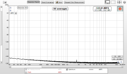
Still playing with E-MU 0404 USB. This time REW analyzer.
Joint-sides calibration at 48kHz, balanced loopback.
First screenshot no distortion added.
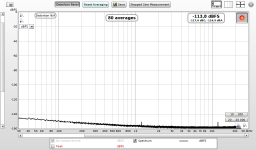
Second screenshot added distortions -140dB at 2nd, 3rd, 4th harmonics to playback side.
I think it will be a decent measurement card.
Joint-sides calibration at 48kHz, balanced loopback.
First screenshot no distortion added.
Second screenshot added distortions -140dB at 2nd, 3rd, 4th harmonics to playback side.
I think it will be a decent measurement card.
Attachments

Slowly learning REW - disabled peaks view.
1) Loopback corresponds to specs DAC THD+N 0.001% + ADC THD+N 0.0009% => approx 0.002%
2) Joint-sides compensation
3) Added playback-side distortions 2nd + 3rd + 4th @ -145dB
1) Loopback corresponds to specs DAC THD+N 0.001% + ADC THD+N 0.0009% => approx 0.002%
2) Joint-sides compensation
3) Added playback-side distortions 2nd + 3rd + 4th @ -145dB
Attachments

E-MU 0404 noise floor at no input and 1211Hz@-1dB output. The input TRS sockets ground both inputs when no connector is inserted.
Right input channel shows no signs of the output signal, the left input channel has the signal at -150dB.
Unfortunately the compensation cannot compensate hot and cold lines of a single balanced input/output independently.
Balanced LPF would be possible, but balanced voltage divider would either require two precisely matched multiturn pots, or a single-pot balanced VD would present a variable load for the output, changing its distortion profile at each position.
Attachments
Last edited:
I am thinking about practical use of the harmonic distortion compensation for generating long-term clean sine signals at any audio-range frequency.
Currently the tool can run continuous calibration on capture side, reloading the compensation profile every few seconds. The calibration cannot run when measuring DUTs, obviously, the soundcard inputs are needed for the measured signal.
But for generator purposes, the inputs are idle. They could be used for continuous split-sides calibration (one channel sampling LPF, another channel sampling voltage divider -> distortion-split calculation -> incremental update of the playback-side compensation profile). Updating the profile every few seconds should keep the signal constantly low THD. The static parameter is LPF/VD transfer which changes very little and could be re-measured every hour or so, automatically.
A decent low-noise soundcard (pre-owned E-MU 0404 USB, screenshots in previous posts show its potential), a small PC (the quad-core Raspberry Pi3 would likely suffice as no measurement software would be running). Either using the existing tool GUI (mouse, keyboard) or a dedicated control panel with display and push buttons and the multiturn pot for fine-tuning the divider to fit the LPF attenuation at the required output frequency.
In addition, artificial distortions at any level to any harmonic can be added if needed.
Looks like lots of work ahead
I have rewired the calibration adapter for balanced outputs/inputs of E-MU 0404 USB, wrapped the the multiturn pot and all the switches with copper tape, used good-quality microphone cable. The calibration loopback is basically clean of main freq, the adapter does not seem to introduce any significant extra noise.
Split-sides compensated loopback at opamps output level is attached.
Split-sides compensated loopback at opamps output level is attached.
Attachments
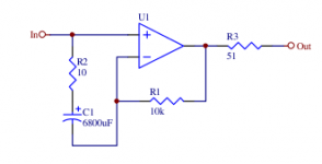
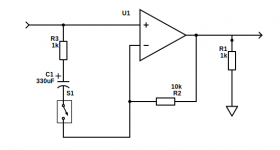
The opamp test board extended with distortion-gain circuit, switchable with a pin header/jumper. The distortion amplification factor should be (10k/1k + 1) = 11x.
The results are ... I do not know. For half of the tested opamps the THD is approx. 10x, for the other half - only very small increase.
Two 4560s where it works:
The results are ... I do not know. For half of the tested opamps the THD is approx. 10x, for the other half - only very small increase.
Two 4560s where it works:
Attachments


During the measuring I incidentally re-measured the same opamp twice (about 20 minutes between measurements) - the results are definitely repeatable.
Attachments


But then there is a number of opamps where the measured distortion does not correspond to the theoretical calculation. For 4556s the was usually 2x, for 5532 the gain was minimal. All the measurements are repeatable to almost same values.
Attachments
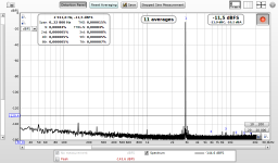
But adding artificial distortion shows the detection works correctly.
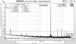
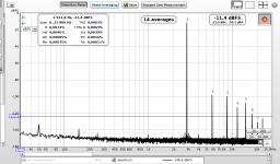
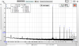
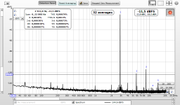
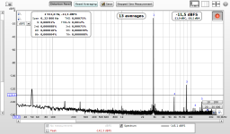
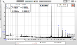
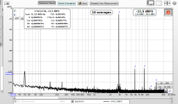
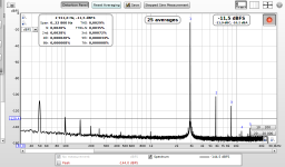
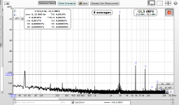
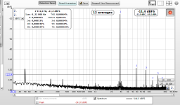
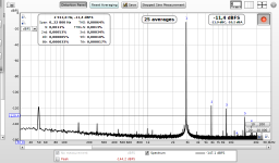
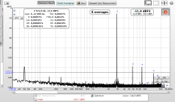
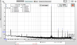
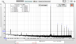
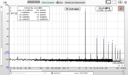
I have remeasured opamp 5 and added distortion to harmonics which was originally low, so that the result was visible. The loop gain is -10dB (output -1.5dB, input -11.5dB), therefore I added -130dB which should result in -140dB in the spectrum. And it is there, as it should be.
Screenshots
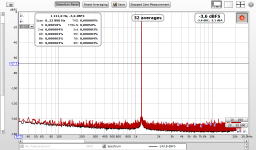
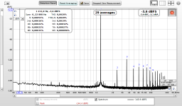
1) the original opamp 5 spectrum
2) remeasured opamp 5 spectrum after about an hour
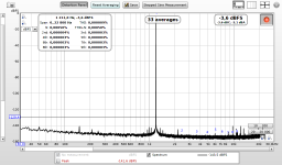
3) added -140dB distortion to 4th harmonics
I do not know why some of the opamps did not respond to the gain amplification but the method seems to measure correctly, at least in my opinion. I think it would require a pre-measured opamp from some other device.
I have remeasured opamp 5 and added distortion to harmonics which was originally low, so that the result was visible. The loop gain is -10dB (output -1.5dB, input -11.5dB), therefore I added -130dB which should result in -140dB in the spectrum. And it is there, as it should be.
Screenshots
1) the original opamp 5 spectrum
2) remeasured opamp 5 spectrum after about an hour
3) added -140dB distortion to 4th harmonics
I do not know why some of the opamps did not respond to the gain amplification but the method seems to measure correctly, at least in my opinion. I think it would require a pre-measured opamp from some other device.
Attachments
I do not know why some of the opamps did not respond to the gain amplification but the method seems to measure correctly, at least in my opinion.
There could be some (phased) cancellation with the additional distortion introduced by the capacitor. I know that would be very minuscule, but this is very minuscule country. Is it possible to do it without the cap, only the resistor, just to exclude the possibility?
Jan
I do not know. If you look at the spectra of opamps where the amplification did not yield the expected result, their harmonics are quite high (> -110dB). IMO the capacitor distortion cannot be so large, otherwise it would affect measurements of the "well-behaving" opamps plus their measured max. harmonic was much lower. Nevertheless I will try to bypass the capacitor and see the effect, it's a trivial modification.
The S. Groner's study http://www.nanovolt.ch/resources/ic_opamps/pdf/opamp_distortion.pdf talks about three types of distortion. The study states that the common-mode and output distortion types can be of comparable magnitude. Yet I am amplifying only the common-mode one, the other type requires a different circuit. Theoretically, perhaps the three opamps "resistant" to common-mode amplification have their output distortion higher, and amplifying the common-mode distortion alone did not yield the increase in their overall distortion at its expected level.
There is always a clearly visible overall increase, just not so high. The study says the common-mode distortion is dominated by 2nd harmonic - the spectra of "resistant" opamps clearly show increase in their second (and fourth) harmonic, while the third mostly remains intact (or even drops in one case).
Most people/sources mention amplifying the common-mode distortion by 100 or even 1000 (40dB, 60dB). That would certainly override the otherwise dominating other distortion type, if that was the case. However, I have amplified only by 10, not to be able to actually detect the amplified harmonics, but to see the details of their change. Maybe this is how the opamps really behave at these low distortion levels Or maybe not.
But how do we find out?
I will raise the amplification to the "recommended" value of 100 and re-measure.
The S. Groner's study http://www.nanovolt.ch/resources/ic_opamps/pdf/opamp_distortion.pdf talks about three types of distortion. The study states that the common-mode and output distortion types can be of comparable magnitude. Yet I am amplifying only the common-mode one, the other type requires a different circuit. Theoretically, perhaps the three opamps "resistant" to common-mode amplification have their output distortion higher, and amplifying the common-mode distortion alone did not yield the increase in their overall distortion at its expected level.
There is always a clearly visible overall increase, just not so high. The study says the common-mode distortion is dominated by 2nd harmonic - the spectra of "resistant" opamps clearly show increase in their second (and fourth) harmonic, while the third mostly remains intact (or even drops in one case).
Most people/sources mention amplifying the common-mode distortion by 100 or even 1000 (40dB, 60dB). That would certainly override the otherwise dominating other distortion type, if that was the case. However, I have amplified only by 10, not to be able to actually detect the amplified harmonics, but to see the details of their change. Maybe this is how the opamps really behave at these low distortion levels
Or maybe not.But how do we find out?
I will raise the amplification to the "recommended" value of 100 and re-measure.
Last edited:
I have added another switchable resistor parallel to the amplification one. Now the gains are 1x, 11x, 48x.
The extra components catch slightly more of the 50Hz mains compared to yesterday spectrum.
The two opamps which "behave good" simply behave good at any gain.
4556 nb. 1, ordered by distortion gains:
1) 1x from yesterday - THD 0.00058%
2) 1x - THD 0.00061%
3) 11x - THD 0.0064% => 10.5x
4) 48x - THD 0.032% => 52x
Comparison of harmonics yesterday vs. today:
2nd 0.00042% 0.00040%
3rd 0.00036% 0.00041%
4th 0.00076% 0.00076%
5th 0.00016% 0.00017%
6th 0.000030% 0.000027%
7th 0.000009% 0.000013%
Attachments

- Home
- Design & Build
- Equipment & Tools
- Digital Distortion Compensation for Measurement Setup