My project deals with static measurement signal. The initial trials with polynomial transfer functions (which is probably what ESS does) did work to some extent, but selective generation of specific harmonics at opposite phase is far more effective for the purpose. The project cannot compensate a random signal, it must measure phase of the fundamental and apply correction harmonics at correct phases. For measuring correct phase the fundamental must be stable freq for at least a second - sweep would not work either.
However, it accepts any form of signal, it just stops adding the compensation signal the moment no known fundamentals are detected. The incoming signal analysis runs continuously, at any time.
Second side-effect is generating clean harmonic signal - cleaning DAC output via the split-sides compensation, again at specific frequency.
Just for modifying the transfer curve - e.g. the modified alsa-lib route plugin nonlinear-compensation/Working_polynoms.patch at 6d031a33d23c1a0cc898cb6247515a8ec39217c2 * pavhofman/nonlinear-compensation * GitHub is usable if you know the coeffs. Again, my polynomial version was determining the coeffs for a specific harmonic signal only. Each frequency resulted in different coeffs. Perhaps some averaged version would reflect the static nonlinearity of the chain, I never tried that. Static polynomials could not rotate all harmonics exactly at -180° which made me look at a different more direct-approach technology.
But the octave/playrec combo could quite easily be used for the polynomial compensation e.g. on windows where no configurable audio layer like linux alsa exists. The principle would be similar to my project, just less complicated - no incoming signal analysis needed. Theoretically the project could be modified to calibrate polynomials and apply the averaged polynomials for a general signal. There would be many issues to solve - e.g. interpolating between calibrated/averaged coeffs for various input levels: what is immediate level of a general signal. In my case it is simple - it is the level of the fundamental obtained by FFT in the current 200ms cycle.
it is adjustable, not just on/off. They use 16-bit signed int registers with the midpoint, zero, being no correction. They suggest the registers could be used to compensate for non-linearities in the external analog electronics. I think if you want to know more, you will have to get a data sheet and or talk to them.
Ahhh, OK, I get that. So you could for instance 'twist' the transfer curve a bit to compensate for the 2nd of a SET poweramp down stream. Hm.
Jan
For tweaking second harmonics (SET) you can use the second chebyshev polynomial. I use them for generating distortions to the incoming signal in DISTORT mode nonlinear-compensation/config.m.example at 1af079f194b6784a1b3a439df9a2f05d802d7cc9 * pavhofman/nonlinear-compensation * GitHub
The question is what gain to apply for the polynomial.
The question is what gain to apply for the polynomial.
Second side-effect is generating clean harmonic signal - cleaning DAC output via the split-sides compensation, again at specific frequency.
If I understand what you mean correctly, you intentionally add opposite phase harmonics analyzed by the split-sides compensation to cancel inherent DAC harmonics at the specific frequency and amplitude, i.e., 1kHz 2Vrms. I'm sure this can work successfully. I will do try this after my environment has fixed. It's very useful technic to have a clean oscillator with arbitrary frequency and amplitude which can be locked to an external reference signal.
The software is getting forward slowly but steadily, over 260 commits GitHub - pavhofman/nonlinear-compensation: Compensation of nonlinear sound card distortions for audio measurements but still lots to go. Octave‘s GUI capabilities are rudimentary but sufficient for this task.
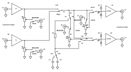
The next step now is coding the actual calibration process using real soundcard measurement adapter. For that either a more complete version of https://www.diyaudio.com/forums/att...mpensation-measurement-setup-tool-diagram-png with switches and potentiometer can be hacked.
Or a proper/final version with arduino-controlled relays is designed/built/written support for in octave.
I would like to ask those experienced with soundcard adapters for comments on this plan:
DAC Side:
--------------
soundcard stereo output -> stereo opamp unit buffer with decent output power -> stereo output voltage divider (75Ohm resistance?). The voltage divider will be connected permanently, even during calibration, to keep the distortion constant. Output terminals relay-switched between divider outputs (measuring) and ground (calibration).
The output divider made of 4 DPDT relays, yielding 16 steps, 3dB each, max. attenuation -45dB. Each step for each channel pre-calibrated in software (no need for precision resistors) to allow for decent balanced output with each branch (in fact L/R channels) distortion-compensated (enabled/disabled in the GUI control panel).
ADC Side:
--------------
stereo input voltage divider (50kOhm?) -> overvoltage protection with low-leakage clamp diodes to +/-3V -> stereo opamp buffer relay-switchable gain1x/10x -> soundcard stereo input
Calibration Loop
--------------------
Loop taken from output of the output buffer -> one channel of the input voltage divider used for calibration at exact current input level -> input buffer
Distortion of the output buffer will be compensated as part of the DAC side, distortion of the input buffer will be part of the ADC side. Thus no expensive ultra-low distortion opams are needed.
Since calibration is very sensitive to input level, the voltage divider must attenuate the calibration signal to fit the measured signal level very closely. Analysis keeps measuring current level at all times, relay-based attenuator is easy to control. 9 relays = 9 bits = -51dB attenuation at step 0.1dB which is small enough as tested. Again, no precision resistors required since calibration does not require precisely defined steps (interpolation works OK) and virtually-balanced inputs will have each step of each channel automatically pre-calibrated. Regular E24 series will do.
During calibration: adapter outputs are grounded, adapter inputs are disconnected/NC.
Total number of DPDT relays about 20, assumed TQ2/5V, 20 pcs at 20USD. Octave -> arduino package -> USB port -> Arduino with built-in usb-serial adapter (2USD CH340, 5USD FT232) -> ULN2003 drivers -> relays.
Power supplies:
-------------------
Buffers: +/- voltages taken from the soundcard – solves the problem of ground loops too.
Relays: 5V max 1A total – two USB ports paralelled, one used for communication with USB-serial adapter of arduino.
Soundcard
--------------
In order to avoid any ground loops a laptop powered from batteries is preferred (even class II power brick introduces the loop through its Y-class capacitor). Thus either a good USB soundcard with no 1kHz residuals (expensive), or PCI/PCI-e (ESI Juli, Xonar Essence) with Expresscard-> PCI-e/PCI adapter (35USD) and decent generated +/- voltages from 5V of the expresscard slot.
Laptop CPU - min. i3/i5, 4 threads. Refurbished good units with expresscard slots (HP, Lenovo TP) running at 150+ USD, new battery at 50+ USD. Should allow for 3+ hours of continuous measurement on battery.
Last edited:
Jan, I very much appreciate your generous offer. Your technology is without doubt top class. For now I am thinking of something a bit cheaper as the better PCI(e) soundcards already do a decent job filtering their power supplies. The thing is I want to keep it as simple/affordable as possible.
Better soundcards usually have decent step-down regulators. A few years ago I tested noise bottom of ESI Juli put into a thin-client PC powered by a 20V power brick. There was no measurable difference when the analog part of the soundcard was powered from the PCI slot directly (i.e. the PCI +/-12V voltages were generated by some noisy onboard switched source) vs. when I cut the Juli's internal header connector leads and supplied external +/-12V from linear PSUs with a regular dual-winding transformer.
The expresscard -> PCI(e) adapter itself makes the tool more expensive, almost half price of the actual (second hand) soundcard. Maybe I will find a way to clean/improve the built-in switched supplies onboard the adapter/s.
I want to keep the digital-format adapters/soundcard/measurement adapter in a separate shielded enclosure, with the PCI(e) part in a separate compartment. A metal case + 3D printed internal structures shielded with grounded copper tape.
Last edited:
OK, adding one or two extra chips on the adapter board is no complication. Please any suggestion for the output buffer opamp? The buffer will be part of DAC-side compensation, output power is more important than ultra-low distortion, IMO.
For input I am thinking of OPA2134UA, I already have those.
I wonder about input coupling caps - film EPCOS 10uf/100V (2USD each)? They will not be part of the distortion-compensated ADC side, thus low distortion is important. I already have the epcos from an ebay seller with good references on eevblog forums.
I see some soundcard adapters use 100kOhm input divider. I want to keep noise as low as possible - would only 50k do? Or even less, similar to input impedance of soundcards (30k)?
Thanks a lot for any hints.
For the output buffer I tend to go with OPA604. Max. current 40mA is OK for max 2V to 75ohm output divider = 26mA, unit-gain stable, inexpensive. Single version for better PCB layout and separate power filtering. I do not want any additional interchannel distortion which is impossible to compensate - in the virtual balanced output mode each channel will run in the opposite phase.
Unfortnately the OPA604's distortion may be a limiting factor even if you try to correct it. For low impedance drive there are some new chips designed for headphones that have significantly lower distortion. New Audio Op Amp - OPA1622 Or add a buffer for the current. Even if you can correct for distortion its probably better to minimize extra sources.
For the input it depends on what you are testing. If a preamp can't drive 10K I consider it borderline broken. Most analyzers are 100K in. A divider with 100K should be fine. Use larger resistors. 1/2W through hole or similar thin film SMT. You should not need any compensation caps if the impedances are low (10K or less). 100K may need a samall parallel cap to compensate for the load capacitances.
If testing a power amp you can use the load resistors as part of a divider network.
KSTR's work on looking at very low level linearity is interesting and relevant: [solved] RME Adi-2 Pro FS (AK4490 DAC): positive sample values are always offset by -1 ! | Audio Science Review (ASR) Forum
Input noise- again most analyzers are 100K in. The typical best practice gets around 5 nV/rtHz noise. Its hard to get lower with a practical destruction resistant input. The 3V range usually goes straight in. 10V, 30V, 100V are divided. Below 3V is amplified at the input. I can provide the input circuits of several good analyzers as a starting point. I have tried a variety of opamps for that service and the best I have tested so far were LME49710's in a differential input with an AD797 as the differential amp. It still can have some input distortion from input C modulation. Getting better really requires discrete circuits.
Hi Demian,
I very much appreciate your info.
OPA1622 - of course I would love to use the newest/most modern components. 145mA output current looks great. The package is rather DIY unfriendly, nevertheless the ebay DIP8 kits may be genuine since they cost slightly more than single quantities of the chip itself from reliable distributors.
Input divider - Honestly I would like to avoid the compensation capacitors. The goal of my project is creating a low-cost very low-distortion measurement setup using decent but still common soundcards (100USD pre-owned). These soundcards are not exactly ultra low-noise. I am not aiming at competing with AP (yet") ) I would prefer lower input impedance/lower noise/no compensation caps to input stage with high impedance which is difficult to make low-noise/compensate with caps.
) I would prefer lower input impedance/lower noise/no compensation caps to input stage with high impedance which is difficult to make low-noise/compensate with caps.
As of input amps - do you think LME49710 for switchable 1x/10x gain would be OK? I will design the PCB for mono SOIC8 version and any opamp can be used.
I very much appreciate your info.
OPA1622 - of course I would love to use the newest/most modern components. 145mA output current looks great. The package is rather DIY unfriendly, nevertheless the ebay DIP8 kits may be genuine since they cost slightly more than single quantities of the chip itself from reliable distributors.
Input divider - Honestly I would like to avoid the compensation capacitors. The goal of my project is creating a low-cost very low-distortion measurement setup using decent but still common soundcards (100USD pre-owned). These soundcards are not exactly ultra low-noise. I am not aiming at competing with AP (yet
) I would prefer lower input impedance/lower noise/no compensation caps to input stage with high impedance which is difficult to make low-noise/compensate with caps.As of input amps - do you think LME49710 for switchable 1x/10x gain would be OK? I will design the PCB for mono SOIC8 version and any opamp can be used.
I can provide the input circuits of several good analyzers as a starting point.
Well, that is a very tempting offer
Input divider - Honestly I would like to avoid the compensation capacitors.
Working on my new AR MK II I realized that for input Z of 10k you most probably can get by without attenuator comp caps, certainly out to 100kHz, which I think is reasonable.
And nowadays even tube equipment can generally drive 10k without much problems.
Jan
I wonder what is the procedure for setting the compensating capacitor value at frequencies close to fs/2 where no high-bandwidth "rectangular" signal can be transferred to look at compensation effect? Measuring absolute transfer value for various frequencies? That would also compensate varying frequency amplitude transfer for the rest of the ADC chain.
IMO the attenuator could be frequency-compensated mathematically in octave instead of trimming capacitors, likely much more precisely.
IMO the attenuator could be frequency-compensated mathematically in octave instead of trimming capacitors, likely much more precisely.
- Home
- Design & Build
- Equipment & Tools
- Digital Distortion Compensation for Measurement Setup