One possibility that makes more sense- a low pass filter will shift the phase of the harmonics. If there is cancellation between source and ADC instead of a removal of harmonics the phase shift of the low pass filter will cause the harmonics to not decrease per the 6 dB/octave they should. It would be an indicator that there is cancellation between source and ADC creating an illusion of no distortion. You would need a very good (polystyrene) capacitor and film or foil resistor for the filter.
I have mint running and will be setting up octave and playrec this weekend I hope. I need more details on the Alsa configuration. Maybe you can share so I have some pointers. I have not fiddled with Alsa for at least 5 years. Its probably quite different.
I can start with a Juli card to get the software working. Then move the RTX to that system. Is the ALSA support for XMOS stable enough for that to be trouble free? Are the drivers for the EMU and the RME included in Mint or do I need to compile and install?
One possibility that makes more sense- a low pass filter will shift the phase of the harmonics. If there is cancellation between source and ADC instead of a removal of harmonics the phase shift of the low pass filter will cause the harmonics to not decrease per the 6 dB/octave they should. It would be an indicator that there is cancellation between source and ADC creating an illusion of no distortion.
What do you mean by source, the DUT?
The split-sides calculation uses measured (i.e. joint-sides) distortions from the voltage divider (VD) and from LPF. LPF rotates the phases (by tens of degrees, not multiples of 360°). They can be hidden by cancellation either in VD measurement, OR in LPF measurement. But not in both.
Let's assume it is zeroed in VD. Sine in refVD will be zeroes nonlinear-compensation/calculateSplitCal.m at b8cff0d50edc9aa7aa2d48ed7746f23a684b010f * pavhofman/nonlinear-compensation * GitHub (since distortAmplVD = 0)
Sine in refLP will NOT be zeroes nonlinear-compensation/calculateSplitCal.m at b8cff0d50edc9aa7aa2d48ed7746f23a684b010f * pavhofman/nonlinear-compensation * GitHub (since distortAmplLP != 0)
In the fitting eqs the sum of DAC and ADC distortions for the VD case will be fit to zero nonlinear-compensation/vdlpEqs.m at b8cff0d50edc9aa7aa2d48ed7746f23a684b010f * pavhofman/nonlinear-compensation * GitHub . It can be zero in two cases:
A) either both sineD_VD and sineA_VD vectors with calculated sines are zero, or
B) they are nonzero, but just have opposite phases and cancel out each other - exactly what would have happened in reality.
The fitting procedure must satisfy values for LPF case at the same time. The sum for the LPF case (measured refLP) will not be zero nonlinear-compensation/vdlpEqs.m at b8cff0d50edc9aa7aa2d48ed7746f23a684b010f * pavhofman/nonlinear-compensation * GitHub . Therefore the least-squares fitting cannot converge to the option A) but must fine-tune the distortion amplitudes and phases so that they cancel out for sineVD (sineVD -> refVD which is all zeros) and not cancel out for sineLP (sineLP -> refLP which is not zeros).
You would need a very good (polystyrene) capacitor and film or foil resistor for the filter.
That will be needed for highest-quality splitting of DAC/ADC distortions too. The principle assumes the LP filter introduces no distortions itself. IMO for regular soundcards with noise floor around -140dB any decent capacitor/resistor will do.
The actual LPF distortion can be incorporated into the calculation quite easily. But it must be known in advance - most users will not have a means to measure that precisely.
I have mint running and will be setting up octave and playrec this weekend I hope. I need more details on the Alsa configuration. Maybe you can share so I have some pointers.
I will write detailed installation instructions for alsa config, pulseaudio config, wine config for e.g. Arta, playrec compilation on github wiki. Please allow for a few days, right now I have to finish cleaning the splitting procedure so that the calibration does not involve all the measurements every time, but allows for separate measuring the stable params (VD/LPF transfer params) and the unstable params (soundcard distortions). VD/LPF transfer measurements take more time since they run for all harmonics up to fs/2 and will not change much in time - no reason to run them every time a calibration at specific output/input level is required/run.
I can start with a Juli card to get the software working.
Great, the best card for starting.
Then move the RTX to that system. Is the ALSA support for XMOS stable enough for that to be trouble free?
XMOS support is stable, it is a standard USB-audio v.2 protocol. If it does not implement any extra features, it should run out of the box, just like that EVGA NU Audio PCI-e soundcard we discussed recently does https://www.diyaudio.com/forums/pc-...e-music-server-player-os-342.html#post5756401
Nevertheless I would assume people have already tested RTX in linux if it uses regular XMOS.
Are the drivers for the EMU and the RME included in Mint or do I need to compile and install?
All alsa drivers are part of linux kernel source code, Mint/Ubuntu being a general-purpose distribution compiles all sound modules.
Last edited:
I don’t think the EMU cards work in Linux out of the box, at least, not in Debian 7 years ago when I tried. The EMU 10k1 controller driver is in the tree and loads fine, but at least for the 1820m you need to load dock firmware for it to work. Without that it’s sort of like having the driver loaded in Windows but without the patchmix application running.
There are a few guides you can find via Google but I’ve never tried them. It may depend on if that firmware is now distributed by default, or its “non-free” and you just have to manually get alsa-firmware.
There are a few guides you can find via Google but I’ve never tried them. It may depend on if that firmware is now distributed by default, or its “non-free” and you just have to manually get alsa-firmware.
Last edited:
Thanks for the update. I have never had any EMU card, no experience.
Let's start with the easiest option - Juli. Eventually the windows version should happen, will just take some time. The playrec windows compilation is still on the TODO list.
I may rewrite the project in java later on, if it turns out to make sense. Java has good audio support on all major platforms and is WAY more productive to develop")
Let's start with the easiest option - Juli. Eventually the windows version should happen, will just take some time. The playrec windows compilation is still on the TODO list.
I may rewrite the project in java later on, if it turns out to make sense. Java has good audio support on all major platforms and is WAY more productive to develop
I have made it part way through. Playrec is not so straightforward and I will need to return to this later. The RME is well supported and has a full UI available. The EMU is not supported out of the box so I'll need to figure out the next steps.
I'll move to the system with the juli soon after getting the playrec working.
Maybe I should look at getting this running under windows. A different set of problems but some pieces are better supported.
I'll move to the system with the juli soon after getting the playrec working.
Maybe I should look at getting this running under windows. A different set of problems but some pieces are better supported.
I will write up the playrec compilation procedure on the wiki, perhaps tomorrow evening. It works almost out of the box.
Windows requires playrec compiled. I have not managed to do that yet, way more complicated than on linux for me. I am trying to find someone skilled with windows development.
Windows requires playrec compiled. I have not managed to do that yet, way more complicated than on linux for me. I am trying to find someone skilled with windows development.
Please follow these simple steps. Should take just a few minutes total.
Playrec Compilation on Linux * pavhofman/nonlinear-compensation Wiki * GitHub
Playrec Compilation on Linux * pavhofman/nonlinear-compensation Wiki * GitHub
I will write up the playrec compilation procedure on the wiki, perhaps tomorrow evening. It works almost out of the box.
Windows requires playrec compiled. I have not managed to do that yet, way more complicated than on linux for me. I am trying to find someone skilled with windows development.
If I had more time I'd give it a try. It should be easy enough to compile Playrec on Windows if you have the right versions of the prerequisites. It looks like you need Visual Studio, the Windows SDK, and Octave or Matlab. I think I saw a CMake script for Playrec once that might generate you a Visual Studio project or solution.
It's still easier under Linux, though.
phofman, I think there's a very interesting exploit to consider that simplifies the math. The phase shift from the LPF is a very clever idea to try and constrain the system, but try as I might, I cannot derive the equations to unconditionally constrain.
However, if you first measure the combined ADC and DAC distortions using the non-inverting input of an analyzer, and then make another combined measurement of ADC and DAC distortions going into the inverting input of an amplifier, then you get the following simple math:
Dd + Da = X (measurement into non-inverting input)
-Dd + Da = Y (measurement in inverting input)
Then the math simplifies to Da = (Y+X)/2 and Dd = X-Da.
The above are complex quantities. The inversion is key. Without the inversion, you have two unknowns, but no matter what with the LPF you don't get two distinct equations it seems to me.
The phase shift from the LPF is a very clever idea to try and constrain the system, but try as I might, I cannot derive the equations to unconditionally constrain.
The two equations are in nonlinear-compensation/vdlpEqs.m at master * pavhofman/nonlinear-compensation * GitHub , I posted the link here recently.
However, if you first measure the combined ADC and DAC distortions using the non-inverting input of an analyzer, and then make another combined measurement of ADC and DAC distortions going into the inverting input of an amplifier, then you get the following simple math:
Dd + Da = X (measurement into non-inverting input)
-Dd + Da = Y (measurement in inverting input)
Then the math simplifies to Da = (Y+X)/2 and Dd = X-Da.
The above are complex quantities. The inversion is key.
Have you actually tried to compute some results in your software? It should be quite easy to modify, IMO.
Da is derived from the fundament. The fundament is inverted by the invertor too, along with Dd. IMO the invertor equation is:
-Dd - Da = Y
Which is again dependent on the first one.
Without the inversion, you have two unknowns, but no matter what with the LPF you don't get two distinct equations it seems to me.
One equation for VD, another equation for LPF.
VD:
Dd + Da = X
LPF:
K * Dd + L * Da = Y
Where K is complex transfer of LPF at Dd freq and L is complex transfer of LPF at fundamental freq, adjusted for Da freq.
For calculation I do not use complex numbers because the
nonlin_curvefit function of octave does not like them. I fit pre-calculated sine series in time domain, results should be the same.
Which is again dependent on the first one.
Ah, yes, you are right. The cleverness of the LPF for breaking these apart becomes even more clever
I'll continue to studyI am thinking about split-calibrating the dual-tone signal (joint-sides dual-tone compensation works perfect, for frequencies both divisable by their difference - 10+12kHz OK, 11+13kHz not OK).
In this case the fundamentals behind VD and LPF differ as LPF attenuates the second tone more than the first one. Different fundamentals mean different distortion profiles. The distortion fitting works only for fundamentals of same level and structure.
I think the dual-tone splitting could be calculated by using four equations for four distortions. Let's assume fundamentals F2 > F1, all at -7dB:
VD filter just scales both fundamentals:
(1) VD filter: F1@-7 + F2@-7dB -> (VD@-6dB) -> F1@-13 + F2@-13dB
LP filter attenuates F2 by -2dB below F1:
(2) LP filter: F1@-7 + F2@-7dB -> (LPF) -> F1@-13 + F2@-15dB
DAC generates F2 attenuated by -2dB, so that output of VD produces the same fundamentals as in (2) with the same ADC distortion profile:
(3) VD filter: F1@-7 + F2@-9dB -> (VD@-6dB) -> F1@-13 + F2@-15fB
Obtaining output of (1) for input of (3) requires attenuating the first fundamental F1 by -2dB - we need a high-pass filter:
(4) HP filter: F1@-7 + F2@-9dB -> (HPF + some VD scaliing) -> F1@-13 + F2@-13dB
Here we have 2 fundamental combinations on DA side, 2 fundamental combinations on AD side, 4 measured joint-sides distortions, 4 equations using all the 4 fundamental combinations (searched-for values). VD/LPF/HPF params for each distortion frequency are known - measured precisely in advance - just like for single-tone.
IMO these four equations should be mutually independent and fitting them the same way as for single-tone (distortions adjusted for time and amplitude difference) should yield the four distortion values (DA@-7+-7, DA@-7+-9, AD@-13+-13, AD@-13+-15) for any/all distortion freqs.
Out of these four results only the DAC distortion for eq (1) would be used for compensating the DAC at the measurement signal -7+-7dB. The corresponding ADC distortion would be precisely measured consequently by single-side calibration of AD side, with level set close to the last-measured DUT output level by the VD (as already performed by the current tool version for single-tone signal).
The key would be creating the HP filter with inverse effect of the LP filter on the fundamentals. IMO if the RC LP filter worked at the -6dB/oct region, then using another RC HP filter at the +6dB/oct region + correct scaling with a voltage divider to obtain the same input values as in the corresponding equation should do the trick. Perhaps so
Last edited:
Yesterday afternoon I attempted a simplified first try at building what phofman has built and the results are, to me, staggering.
In this implementation the Dd and Da terms are calculated from the two measurements X (pass through) and Y (through LPF), but all the cancellation is currently put in the DAC. As a result, re-inserting the LPF doesn't hold. But I'll fix that in the coming week.
The LPF is a 3.3K and 33nF NP0. The filter was swept and exported. System was configured for pass through, a single cycle was run. And then that measurement was captured as "phase 1". System was configured as LPF, and then another single cycle was run and that was captured as "phase 2" using the previously exported filter data.
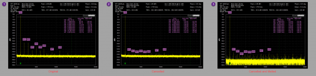
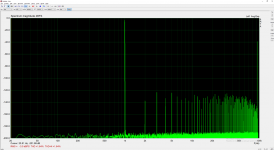
In the attached, you can see 3 plots. Plot 1 is the QA401 at 0.5 dB away from max output limit and thus harmonics are growing. Harmonics are around -100 dB. Plot 2 is with cancellation active. Harmonics are -138 and lower. Plot 3 is with cancellation and melt active. Melt is an experimental mode on the QA401 that was prompted by a discussion with Demian years back after he'd sent a paper on paralleling ADCs. It basically sums N coherent time-domain acquistions, and then performs FFT on the average. This drives noise to zero. If you wait long enough, the THD+N will converge to THD because you have "melted" the noise. Here, it's useful to peel back the noise and see where the harmonics are.
Some interesting observations to bolster what phofman has seen. First, the filter only needed to be swept once. That one capture has been used over and over to reproduce this. Second, the results held over night. IOW, the coeffs determined 12 hours ago still "work". There is a fairly large temperature sensitivity, however. If I hit the DAC or ADC with cold spray, all is lost: the harmonics come back up and don't ever really go back to where they were. The input/output opamps don't seem nearly as sensitive though.
Implementation details:
This is all polar math and ham-fisted at this point. Phase 1 is capturing pass through value of X = Dd+Da. Phase 2 is capturing with LPF inserted Y = LPF*Dd + Da. This is a slight simplification of phofman's solution that will only hold (I think) if there's no gain in DUT.
For each step, the waveform is aligned to give the same alignment as the DAC output buffer. Post DAC, there are a few sources of delay, on the order of 10's of microseconds. The shfiting is done by a well-known FFT property such that you can take a time series, convert to freq domain, add a linear phase to every point, and convert back to time domain. This permits precise sub-sample shifting if needed. With Phase 1, it's shifted to the correct location and then the amplitude and phases of each harmonic are noted. Amplitudes are stored as relative to fundamental. Phases are absolute. In phase 2, the same is done. At this point, Dd and Da for each point can be computed and you get the values needed in both the ADC and DAC required to offset the offenders. From that point on, the DAC and ADC corrections are applied ot the DAC output. As noted above, that needs to be split in order for anything other than passthrough to work.
I cannot emphasize enough how clever I think the measurement through the LPF is to allow these the dac and adc components to be learned. Phofman, that exploit you shared is awesome.
In this implementation the Dd and Da terms are calculated from the two measurements X (pass through) and Y (through LPF), but all the cancellation is currently put in the DAC. As a result, re-inserting the LPF doesn't hold. But I'll fix that in the coming week.
The LPF is a 3.3K and 33nF NP0. The filter was swept and exported. System was configured for pass through, a single cycle was run. And then that measurement was captured as "phase 1". System was configured as LPF, and then another single cycle was run and that was captured as "phase 2" using the previously exported filter data.
In the attached, you can see 3 plots. Plot 1 is the QA401 at 0.5 dB away from max output limit and thus harmonics are growing. Harmonics are around -100 dB. Plot 2 is with cancellation active. Harmonics are -138 and lower. Plot 3 is with cancellation and melt active. Melt is an experimental mode on the QA401 that was prompted by a discussion with Demian years back after he'd sent a paper on paralleling ADCs. It basically sums N coherent time-domain acquistions, and then performs FFT on the average. This drives noise to zero. If you wait long enough, the THD+N will converge to THD because you have "melted" the noise. Here, it's useful to peel back the noise and see where the harmonics are.
Some interesting observations to bolster what phofman has seen. First, the filter only needed to be swept once. That one capture has been used over and over to reproduce this. Second, the results held over night. IOW, the coeffs determined 12 hours ago still "work". There is a fairly large temperature sensitivity, however. If I hit the DAC or ADC with cold spray, all is lost: the harmonics come back up and don't ever really go back to where they were. The input/output opamps don't seem nearly as sensitive though.
Implementation details:
This is all polar math and ham-fisted at this point. Phase 1 is capturing pass through value of X = Dd+Da. Phase 2 is capturing with LPF inserted Y = LPF*Dd + Da. This is a slight simplification of phofman's solution that will only hold (I think) if there's no gain in DUT.
For each step, the waveform is aligned to give the same alignment as the DAC output buffer. Post DAC, there are a few sources of delay, on the order of 10's of microseconds. The shfiting is done by a well-known FFT property such that you can take a time series, convert to freq domain, add a linear phase to every point, and convert back to time domain. This permits precise sub-sample shifting if needed. With Phase 1, it's shifted to the correct location and then the amplitude and phases of each harmonic are noted. Amplitudes are stored as relative to fundamental. Phases are absolute. In phase 2, the same is done. At this point, Dd and Da for each point can be computed and you get the values needed in both the ADC and DAC required to offset the offenders. From that point on, the DAC and ADC corrections are applied ot the DAC output. As noted above, that needs to be split in order for anything other than passthrough to work.
I cannot emphasize enough how clever I think the measurement through the LPF is to allow these the dac and adc components to be learned. Phofman, that exploit you shared is awesome.
Attachments
Last edited:
Yesterday afternoon I attempted a simplified first try at building what phofman has built and the results are, to me, staggering.
I am glad it works for you. Honestly, I still do not understand why such solution has not been used for many years. Computer-assisted analyzers have been produced for decades. To use LPF was not a random idea, it was the first obvious answer to the question how to change harmonics in a controlled manner against the fundamental so that two independent equations can be obtained and solved.
First, the filter only needed to be swept once. That one capture has been used over and over to reproduce this.
Yes, measuring the LPF and VD at all required frequencies precisely takes some time. In my latest version the transfer measurements are separated from the much faster splitting calibration.
Second, the results held over night. IOW, the coeffs determined 12 hours ago still "work".
I have the same experience.
There is a fairly large temperature sensitivity, however. If I hit the DAC or ADC with cold spray, all is lost: the harmonics come back up and don't ever really go back to where they were.
That is why the actual calibration must be fast and easily repeatable at any moment of measurement.
Phase 1 is capturing pass through value of X = Dd+Da. Phase 2 is capturing with LPF inserted Y = LPF*Dd + Da.
I did not understand exactly your measurement procedure, but Da is rotated and scaled by the LPF transfer of the fundament frequency:
Y = LPF@Dfreq*Dd + LPF@FundFreq*Da
Your use of compensation on one side only is what I call the joint-side compensation. It always works very nice. You used two components, but the X = Dd + Da equation keeps the results equal to the joint-side value. It works for VD/direct loop. Upon inserting LPF, the distortions shot up again if the LPF equation is not correct.
Also take into account the phase difference between each channel and phase shift of the voltage divider, once you start using it (non-negligible at higher freqs).
This is a slight simplification of phofman's solution that will only hold (I think) if there's no gain in DUT.
DUT gain is actually unimportant when splitting the distortion.
1) Split-calibrate distortions at the required DAC level (which is determined by the generator plus changes rarely) (two FFT measurements), use only the DAC part to clean the output signal
2) Measure remaining distortions at ADC side at the DUT level (using voltage divider) (one FFT measurement), compensate
When the DUT output level changes, just repeat step 2), there is no change on DAC side.
For each step, the waveform is aligned to give the same alignment as the DAC output buffer. Post DAC, there are a few sources of delay, on the order of 10's of microseconds. The shfiting is done by a well-known FFT property such that you can take a time series, convert to freq domain, add a linear phase to every point, and convert back to time domain. This permits precise sub-sample shifting if needed.
You use probably the same procedure. FFT directly provides phase shift = time offset, the compensation signal can be calculated with cosine at that time offset. Any phase offset can be calculated at any precision related to the actual sample time.
Amplitudes are stored as relative to fundamental.
You will learn the distortion profile works only for small range around the fundamental amplitude, on both sides. You may want to keep absolute values, you will need them when generating the compensation signal. That is why I use interpolation of distortions for calibrated fundamental levels around the current level.
I cannot emphasize enough how clever I think the measurement through the LPF is to allow these the dac and adc components to be learned. Phofman, that exploit you shared is awesome.
Again, I am glad it works.
Last edited:
> Honestly, I still do not understand why such solution has not been used for many years.
The answer may lie in the obvious limitations of this 'trick', caused by the imperfection of the available DACs (and ADCs). When QAMATt plays more with this solution he will most probably notice that it needs a recalibration for every single level he wants to use. That is not only cumbersome, it also prevents the use of level sweeps. And a usage with frequency sweeps seems unrealistic as well. I also expect termic problems as soon as you want to use this solution to its fullest and need to measure below -130 dB THD.
But I don't want to bash the idea and the execution, it's both ingenious!
it needs a recalibration for every single level he wants to use.
Yes, the distortion profile holds for very narrow margin of the current level. Interpolation of the profile calibrated at a series of levels works, but of course the key is automated calibration - the closer the calibration points are, the more precise profile the interpolation provides.
And a usage with frequency sweeps seems unrealistic as well.
Obviously the profile is for a specific frequency. Again automated splitting the sweep into series of frequencies is possible. It will make the measurement much longer though.
The usage I assume is that compensation is not to be used all the time, for all measurements. It is for temporary "zooming" into distortion of a device below native capabilities of the measurement device. Once the measurement (no sweeps) reveals a need for higher distortion resolution, push a calibration button and obtain the zoomed-in measurement.
I also expect termic problems as soon as you want to use this solution to its fullest and need to measure below -130 dB THD.
Termic problems are unavoidable without cooling, not much to do about them. Yet my ordinary soundcard at virtual balanced mode with both channels compensated measured -131dB THD at output -0.1dBFS/input -0.3dBFS https://www.diyaudio.com/forums/equ...nsation-measurement-setup-16.html#post5769926 . I believe a good HW can go lower.
I am surprised how much of the distortions are due to non-random issues. IMO that is a good reason to try to do something about it, to the extent and situations allowed by physics.
I have finally managed to compile a working playrec on Win10 for ASIO. No WASAPI/the other many windows sound systems yet, There are constant problems with header files of Win10SDK/of mingw coming with windows port of octave/of mingw coming with portaudio.
ASIO itself would be OK, but I could not find any ASIO-based loopback tool. So no go for now anyway. I really hate this dumb inconsistent OS.
ASIO itself would be OK, but I could not find any ASIO-based loopback tool. So no go for now anyway. I really hate this dumb inconsistent OS.
Finally managed to compile playrec with ASIO + WASAPI + MME:
Next step was testing Arta + Virtual Cable VB-Audio Virtual Apps
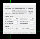
The device is configured to run at 192/24 - see the settings screenshot. Arta is configured the same - see the screenshot
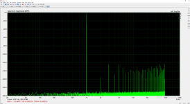
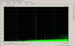
The digital loopback spectrum - see the screenshot. Complete fail, distortion at -120dB, far from bit-perfect.
I tried hooking Asio4All to the virtual cable device and configuring arta to use Asio4All - no change in spectrum. IMO the Virtual Cable is doing something to the signal, no idea what.
At 192kHz the virtual cable fails even more - there is a -40dB peak at 95kHz exactly.
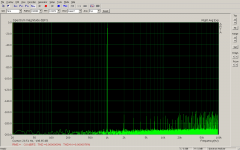
For comparison - the last two screenshots are linux alsa loopback at 96/24 and 192/24 - bit perfect path, as it should be. I am not used to fighting the infrastructure - it is supposed to work 100% correctly.
Should someone try the virtual cable loopback in arta and share the results, I would be very grateful. Perhaps my windows arta is the culprit, I do not know.
Another option for the loopback would be compiling the open source virtual audio wire GitHub - HSpear/virtual-audio-wire: The Virtual Audio Wire (VAW) is an open source Virtual Audio Device (VAD) project its function is to provide Virtual Audio Devices for multimedia applications. . Unfortunately that is outside of my options since I do not own/have never used the required MS Visual Studio (playrec is compiled directly in octave by the included mingw compiler).
Code:
>> test_playrec
Playrec was built with the following defines: DEBUG
Playrec was built with the following host API: MME (6 devices), ASIO (1 devices), Windows WASAPI (4 devices)

Available output devices:
 -1) No Device
  3) Microsoft Sound Mapper - Output (MME) 2 channels
  4) Speakers (2 - High Definition A (MME) 2 channels
  5) CABLE Input (VB-Audio Virtual C (MME) 2 channels
  6) ASIO4ALL v2 (ASIO) 8 channels
  7) CABLE Input (VB-Audio Virtual Cable) (Windows WASAPI) 2 channels
  8) Speakers (2 - High Definition Audio Device) (Windows WASAPI) 2 channels
Next step was testing Arta + Virtual Cable VB-Audio Virtual Apps
The device is configured to run at 192/24 - see the settings screenshot. Arta is configured the same - see the screenshot
The digital loopback spectrum - see the screenshot. Complete fail, distortion at -120dB, far from bit-perfect.
I tried hooking Asio4All to the virtual cable device and configuring arta to use Asio4All - no change in spectrum. IMO the Virtual Cable is doing something to the signal, no idea what.
At 192kHz the virtual cable fails even more - there is a -40dB peak at 95kHz exactly.
For comparison - the last two screenshots are linux alsa loopback at 96/24 and 192/24 - bit perfect path, as it should be. I am not used to fighting the infrastructure - it is supposed to work 100% correctly.
Should someone try the virtual cable loopback in arta and share the results, I would be very grateful. Perhaps my windows arta is the culprit, I do not know.
Another option for the loopback would be compiling the open source virtual audio wire GitHub - HSpear/virtual-audio-wire: The Virtual Audio Wire (VAW) is an open source Virtual Audio Device (VAD) project its function is to provide Virtual Audio Devices for multimedia applications. . Unfortunately that is outside of my options since I do not own/have never used the required MS Visual Studio (playrec is compiled directly in octave by the included mingw compiler).
Attachments
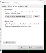
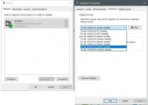
The default behavior of Windows sound engine is to resample any audio it wants to without warning. For each sound device, in Windows control panel there is a default bit-depth and sample rate. If they exactly match your audio then it shouldn't be resampled. Please see attached jpg.
The only way to let an application control the bit-depth and sample rate is to use an ASIO driver AND make sure that the sound device you want to use does not show a green circle with a check mark in it next to the sound device name in Windows control panel. A check mark would indicate it is a default device for some purpose. Best to make some unused sound device the default sound device for every purpose (right click for menu), and then only use an ASIO driver for some other device which is the device you want to use.
The only way to let an application control the bit-depth and sample rate is to use an ASIO driver AND make sure that the sound device you want to use does not show a green circle with a check mark in it next to the sound device name in Windows control panel. A check mark would indicate it is a default device for some purpose. Best to make some unused sound device the default sound device for every purpose (right click for menu), and then only use an ASIO driver for some other device which is the device you want to use.
Attachments
Last edited:
- Home
- Design & Build
- Equipment & Tools
- Digital Distortion Compensation for Measurement Setup