I appreciate your kind offer. The real-world trial requires recompiling alsa route plugin - I have a pcm_route.c version for ubuntu 14.04 and 16.04. Many changes in alsa-lib in recent years, the patch must be rebased for each version to allow compilation of alsa-lib in the distribution version.
If you recorded 5 secs of clean closed-loop stereo data 1kHz -1dB gain 24/32bits generated by sox, for each card, I would do the analysis remotely offline just to test detection and recovery in my script and post the results here afterwards. It would be a great help, thanks.
Got sidetracked by Halloween here (700 kids in 3 hours. . .) I can get the recordings you asked for as wave files recorded in Windows. Most likely I'll use the reference files from RME as a source. They seem to be quite good and are open and available as downloads. Not sure yet which system to use for recording (Audacity, Reaper or maybe Virtins). Let me know if they will work. Otherwise I'll attempt to get the Ubuntu OS working (have not used it in this system for over a year. . . ) One key stumbling block may be the analog level in-out mismatch. At -1 dB it may not be consistent and potential for overload exists. We will find out hopefully tomorrow.
Demian, thanks a lot. My fault, there is actually no need for -1dB level, anything above e.g. -10dB will be OK. You are right, -1dB is too prone to limitations which would ruin the spectrum, we definitely want to avoid them for the test.
The recordings do not have to have equal levels either.
A longer recording would be better (minutes), I can calibrate with the first few seconds and check the calibration validity/effect at several points later in the recording. Thanks!
The recordings do not have to have equal levels either.
A longer recording would be better (minutes), I can calibrate with the first few seconds and check the calibration validity/effect at several points later in the recording. Thanks!
Last edited:
Reverse lookup table created from forward transfer polynomial generates identical results to backward-fitted polynomial. Comparison of their coefficients does suggest this result:
These twin polynomials applied to the sine reference generate identical spectrum, with phases of higher harmonics shifted exactly by 180°:
IMO everything fits theory perfectly, it looks like the code works correctly.
The lookup table approach takes much more RAM and CPU, will be put to sleep for now since we can use the much more efficient polyfit() approach.
All the existing code is available at GitHub - pavhofman/nonlinear-compensation: Compensation of nonlinear sound card distortions for audio measurements . Miero, the participator on this project, has been cleaning it up, adding automation support, etc. Great thanks!
Any suggestions/advice appreciated")
Code:
Backward Polynomial:
  -1.27885985969420e-06   1.00000000000000e+00   2.87402690518208e-06   4.97896833953160e-06   2.57484532189721e-06   9.05667060686485e-05   3.96030020866455e-05  -2.28533634866074e-04  -5.35290382488973e-05
Forward Polynomial:
   1.27557487363966e-06   1.00000000000000e+00  -2.89217431284374e-06  -5.20021199996460e-06  -2.46045556097745e-06  -9.05247434958334e-05  -4.06726318752616e-05   2.30767300229050e-04   5.51924961796381e-05
These twin polynomials applied to the sine reference generate identical spectrum, with phases of higher harmonics shifted exactly by 180°:
Code:
Estimated with forward:
 1000.74 Hz,   -4.13 dB,    0.00 dg
 2001.22 Hz, -116.39 dB,   38.98 dg
 3000.97 Hz, -129.12 dB,  257.96 dg
 4000.71 Hz, -132.31 dB,  116.94 dg
 5001.19 Hz, -123.14 dB,  155.92 dg
 6000.93 Hz, -152.38 dB,  194.90 dg
 7000.68 Hz, -133.99 dB,  233.87 dg
 8001.15 Hz, -155.93 dB,   92.85 dg
    0.00 Hz, -999.00 dB,    0.00 dg
    0.00 Hz, -999.00 dB,    0.00 dg

Estimated with recovery (backward):
 1000.74 Hz,   -4.13 dB,    0.00 dg
 2001.22 Hz, -116.43 dB,  218.98 dg
 3000.97 Hz, -129.87 dB,   77.96 dg
 4000.71 Hz, -132.33 dB,  296.94 dg
 5001.19 Hz, -123.31 dB,  335.92 dg
 6000.93 Hz, -152.81 dB,   14.90 dg
 7000.68 Hz, -134.07 dB,   53.87 dg
 8001.15 Hz, -156.20 dB,  272.86 dg
    0.00 Hz, -999.00 dB,    0.00 dg
    0.00 Hz, -999.00 dB,    0.00 dg
IMO everything fits theory perfectly, it looks like the code works correctly.
The lookup table approach takes much more RAM and CPU, will be put to sleep for now since we can use the much more efficient polyfit() approach.
All the existing code is available at GitHub - pavhofman/nonlinear-compensation: Compensation of nonlinear sound card distortions for audio measurements . Miero, the participator on this project, has been cleaning it up, adding automation support, etc. Great thanks!
Any suggestions/advice appreciated
Last edited:
Sid uses libasound2 v. 1.1.6. The pcm_route.c file in alsa-lib has received quite a few commits in last years History for src/pcm/pcm_route.c - alsa-project/alsa-lib * GitHub
I have ported the patch to 1.0.27 (ubuntu 14.04) and 1.1.0 (ubuntu 16.04). Not yet to 1.1.6, though doable via debootstrap on my ubuntu machine.
Octave is on all debians.
I have ported the patch to 1.0.27 (ubuntu 14.04) and 1.1.0 (ubuntu 16.04). Not yet to 1.1.6, though doable via debootstrap on my ubuntu machine.
Octave is on all debians.
Marcel, thanks a lot for suggestion. I am just afraid we are dealing with such small numbers that any omission creates a visible error.
Are you only afraid of that or did you see that happening? I would expect that when the distortion of the signal is around -100 dB, the distortion of the distortion components will be of the order of -200 dB or less.
As the simplest example, take the instantaneous second-order case:
y = x + alpha x^2
z = y - alpha y^2
z = x + alpha x^2 - alpha (x + alpha x^2)^2 =
x + alpha x^2 - alpha (x^2 + 2 alpha x^3 + alpha^2 x^4) =
x - 2 alpha^2 x^3 - alpha^3 x^4
When x is some sinusoid that varies between -1 and +1 and alpha is 2*10^-5, there is -100 dB of zeroth and second harmonic distortion in y. In z, the worst distortion term is the -2 alpha^2 x^3 term, which gives 1/4 of 2 alpha^2 third-harmonic distortion, or 2*10^-10, about -194 dB.
Marcel, I do very much appreciate your input and effort. You are right about the unimportant higher-order components.
Fortunately it turned out that calculating the inverse polynom is not needed. The inverse lookup table of forward polynom (polyfit(input, output) gives exactly same results as a backward (compensation) polynom (polyfit (output, input)). It means the backward polynom directly identified by least-squares in polyfit is just as optimal as any mathematical calculation of inverse polynom from the forward polynom identified by polyfit.
Fortunately it turned out that calculating the inverse polynom is not needed. The inverse lookup table of forward polynom (polyfit(input, output) gives exactly same results as a backward (compensation) polynom (polyfit (output, input)). It means the backward polynom directly identified by least-squares in polyfit is just as optimal as any mathematical calculation of inverse polynom from the forward polynom identified by polyfit.
Curve-fitted polynomials try hard at rotating the distortion harmonics by 180°, but not all distortions can be attributed to non-linear transfer characteristics. Polynomials cannot reject all distortion harmonics.
A new plain-force approach was chosen - individual distortion frequency components are precisely measured by FFT (calibration) and a compensating signal at correct phase aligned with the fundamental signal rotated by 180° is generated. Works for single sine as well as two-tones (with a minor limitation - each fundamental tone must be dividable by their difference). As of now a single i5 CPU core compensates 40 different distortion frequencies for two channels.
The project is completely coded in octave. The development continues in linux for now, but nothing prevents from running on other OSes. The goal is to build a layer between the soundcard and a virtual loopback soundcard (snd-aloop in linux, virtual cable in windows) which will provide all the features with a simple GUI in octave.
I just added support of the virtual loopback which allows to show some real-time screenshots taken directly from Arta.
Now the next step is trying to split the overall loop compensation between DAC and ADC sides. I want to try to calculate the contribution of each side to the overall distortion harmonics on every frequency using a low-pass filter with precisely known (measured) transfer function. Distortion components generated by DAC are attenuated and rotated by the LP transfer at their respective frequency, while ADC components do not go through the LP filter, they originate instead from the fundamental frequency as it goes through the AD stage - hence attenuated/rotated by LP transfer at the frequency of the fundament. Hopefully the measured harmonic values will allow to determine the amplitude and phase of both components by least-squares estimation of function parameters which has proven very powerful in octave.
Github repo Commits * miero/nonlinear-compensation * GitHub (outdated readme, a few commits behind my master).
Attached screenshots - single and dual tones in mode PASS and COMPENSATE for Infrasonic Quartet, an older but still decent PCI soundcard similar to ESI Juli.
Attachments


Last edited:
Hi, I've been following this. I tried to run it but I get this:
Seems like you forgot to remove the hardcoded file destination in the Octave script. I will try giving it mine instead.
Code:
Input File     : 'hw:1,0' (alsa)
Channels       : 2
Sample Rate    : 96000
Precision      : 32-bit
Sample Encoding: 32-bit Signed Integer PCM

In:0.00% 00:00:03.03 [00:00:00.00] Out:192k  [      |      ]        Clip:0
Done.
error: audioread: failed to open input file '/home/pavel/recorded.wav': System error : No such file or directory.
error: called from
    audioreadAndCut at line 5 column 19
    octave/gen_compen_polynom.m at line 55 column 14
Seems like you forgot to remove the hardcoded file destination in the Octave script. I will try giving it mine instead.
Now I get this:
Here is what I am doing:
I am on Debian Sid.
Code:
$ ./calibrate

Input File     : 'hw:1,0' (alsa)
Channels       : 2
Sample Rate    : 96000
Precision      : 32-bit
Sample Encoding: 32-bit Signed Integer PCM

In:0.00% 00:00:03.03 [00:00:00.00] Out:192k  [      |      ]        Clip:0
Done.
error: fprintf: invalid stream number = -1
error: called from
    octave/gen_compen_polynom.m at line 74 column 1
Here is what I am doing:
Code:
cd ~/tmp/nonlinear-compensation

sudo cp -b ./alsa-lib/xenial-1.1.0/x86_64-linux-gnu/libasound.so.2.0.0 /usr/lib/x86_64-linux-gnu/
sudo cp -b ./alsa-lib/xenial-1.1.0/i386-linux-gnu/libasound.so.2.0.0 /usr/lib/i386-linux-gnu/

sudo /etc/init.d/alsa-utils restart


./calibrate
I am on Debian Sid.
I very much appreciate you want to test. Sorry for the outdated readme. I just erased all the obsolete text.
The project is still in pre-alfa proof-of-concept stage and not really ready for testing. There are major features missing in the core, most of the code will likely change. No reason to deal with patches/pull requests etc for now.
There is/will be no alsa-lib dependency, everything pure octave + forge packages and playrec (current assumption). The calibration tool will use arduino + firmata for controlling the relays. All this technology is multiplatform.
I will announce when it is ready for testing, a matter of several weeks/months. Still a lot of work ahead.
The major breakthrough would be if splitting the DA/AD components works. That would allow generating/feeding DUTs with very clean (perhaps even dual-tone?) signals where all new distortions would be attributed only to the DUT. Right now if the DUT changes a distortion produced by the source side, it affects the compensation, depending on phase/amplitude change by the DUT. Hopefully the precisely-measured low-pass "DUT" will allow to identify contributions of each side. To be seen...
Certainly any ideas are welcome
How about this...
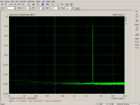
Screenshots:
No compensation:
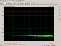
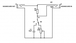
1. PASSING (no compensation) direct loopback through voltage divider
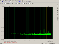
2. PASSING through LP filter (RC) tuned at approx 1kHz - no compensation. Nice to see how the filter attenuates the distortion harmonics
Single-side joined compensation:
3. JOINED-COMPENSATING direct loopback, compensation of the whole loop on ADC side, cleaned
4. JOINED-COMPENSATING through LP filter. The filter changes DAC distortions which corrupts the compensation.
Split compensation of both sides:
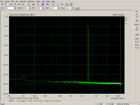
5. SPLIT-COMPENSATING through direct loopback. The measured distortions of direct and LP filter loops are split by parameter fitting of two equations between DAC and ADC sides.
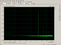
6. SPLIT-COMPENSATING through LP filter. Apparently (almost) no DAC distortions to be affected by the filter to corrupt the compensation on ADC side.
The two split-compensation screenshots are only one switch flip apart - switching from voltage divider to RC filter on the soundcard input while the compensation is running, no change to configuration/restarting the chain etc. There are still minor distortion artefacts on the LP filter spectrum (meaning the DAC signal is not 100% distortion-free) but I hope these can be eliminated by more careful handling gains in the calculation.
I dare to say it works
Screenshots:
No compensation:
1. PASSING (no compensation) direct loopback through voltage divider
2. PASSING through LP filter (RC) tuned at approx 1kHz - no compensation. Nice to see how the filter attenuates the distortion harmonics
Single-side joined compensation:
3. JOINED-COMPENSATING direct loopback, compensation of the whole loop on ADC side, cleaned
4. JOINED-COMPENSATING through LP filter. The filter changes DAC distortions which corrupts the compensation.
Split compensation of both sides:
5. SPLIT-COMPENSATING through direct loopback. The measured distortions of direct and LP filter loops are split by parameter fitting of two equations between DAC and ADC sides.
6. SPLIT-COMPENSATING through LP filter. Apparently (almost) no DAC distortions to be affected by the filter to corrupt the compensation on ADC side.
The two split-compensation screenshots are only one switch flip apart - switching from voltage divider to RC filter on the soundcard input while the compensation is running, no change to configuration/restarting the chain etc. There are still minor distortion artefacts on the LP filter spectrum (meaning the DAC signal is not 100% distortion-free) but I hope these can be eliminated by more careful handling gains in the calculation.
I dare to say it works
Attachments


Last edited:
I am still trying to identify the cause of suboptimal splitting of compensation contributions among the DAC and ADC sides. It is the very key to success of the concept. Clean distortion-free output signal will allow any type of measurement. Compensation on ADC side is then straightforward if we can trust the generated signal to be clean.
I believe the equations describe correctly what the low-pass filter does to the distortions nonlinear-compensation/lpEqs.m at master * pavhofman/nonlinear-compensation * GitHub, nonlinear-compensation/run_splitting.m at master * pavhofman/nonlinear-compensation * GitHub . Yet the result shows some minor peaks in the low-pass filter mode, suggesting the DAC signal is not fully cleaned yet.
I want to try a hard-force approach - finding the correct split with octave's nonlinear optimization/fitting when trying to take the measured LP-mode distortions close to zero Independent parameters in nonlin_residmin . If it works (I do not see any reason it should not) it would be a good starting point towards some faster procedure.
I think it's already quite impressive...
Thanks. Yet without compensation splitting the project has a limited benefit as every DUT will modify the DAC-side distortions and these will not be properly compensated for on the ADC side - see screenshot nb. 4 above.
Is your low-pass filter linear enough?
It is just a simple RC circuit with some old foil capacitor. I assume its nonlinear distortion should be below -130dB.
I measure its gain and phase shift at specific frequencies nonlinear-compensation/measureTransfer.m at master * pavhofman/nonlinear-compensation * GitHub with an automated script nonlinear-compensation/mainCtrl.m at master * pavhofman/nonlinear-compensation * GitHub and use the analysed data in the distortion-splitting equations for each harmonic frequency.
Current splitting code works partially correct:
Switch at VD (voltage divider) - the split-compensation spectrum is clean (see screenshot nb. 5 above).
Upon switching to the LP filter, minor distortions jump up (screenshot nb. 6)
My hard-force idea is keeping the fitting equation for voltage divider mode nonlinear-compensation/lpEqs.m at master * pavhofman/nonlinear-compensation * GitHub, while replacing the low-pass transfer equation nonlinear-compensation/lpEqs.m at master * pavhofman/nonlinear-compensation * GitHub with direct measurements. That means the fitting would measure the resultant compensation quality through the LP filter every fitting iteration which is the most direct way possible. IMO this procedure should work, although it takes much longer since every iteration loop the newly calculated split-sides compensation coeffs must be loaded at both sides and old samples waited for to flush through the chain before measuring the new spectrum as a result of the iteration.
How about the output of the DAC and the input of the ADC, does distortion depend on load or source impedance?
For now I only use my testing tool which has fixed impedances.
Attachments
Last edited:
Finally found the error in ADC-side distortion equation - incorrect gain, as expected Fixed split calibration - correct gain in splitting equation for LP f… * pavhofman/nonlinear-compensation@f04d724 * GitHub
Now I like the spectra for voltage divider and RC LP filter while compensation is running on both DAC and ADC sides. It looks like no detectable output distortions are modified by the LP filter now
Now I like the spectra for voltage divider and RC LP filter while compensation is running on both DAC and ADC sides. It looks like no detectable output distortions are modified by the LP filter now
Attachments

Last edited:
- Home
- Design & Build
- Equipment & Tools
- Digital Distortion Compensation for Measurement Setup