Are you using ASIO or Wine implementation of Windows audio? Is it 24 bit capable? (I have seen complaints elsewhere.)
I am using standard winealsa backend Sound - WineHQ Wiki , Arta talks to regular windows audio layer. Wine does not modify the stream (not that I know of), it just sends samples to its audio backend. Alsa backend turns any application running in wine into a regular alsa application, using all the infrastructure - .asoundrc config with the modified alsa-lib route plugin in this case.
Arta communicates with the soundcard in 32bits.
Also impressive is how easy that was to implement in Linux
Yeah, no way to do such hacks in a closed-source system. I consider software and hardware as equal parts of the final solution. Therefore both must be fully tweakable as situation/project requires.
Modifying pcm_route.c in alsa-lib package to implement the polynom featue was relatively simple. After that I spent the same time learning trial/error how to cross-compile the modified libasound2 library to i386 arch for 32bit wine/Arta on my amd64 ubuntu, a surprisingly complicated procedure
")
I guess your coefficients are fixed one. Do you have a plan to make them variable?
When calibrating the virtual balanced setup I did learn that chaning temperature changes the linear gain of the channels. Since the change is for each channel a little bit different (at fifth decimal point of the linear-gain coefficient), it does affect the CMRR of the setup.
It is possible to make the coeffs tunable while the stream is running. However the question is what values should they have. In order to get precise values you need to run the calibration procedure - it means interrupting the stream, switching some relays controlled by the calibration script etc, and calculate the coeffs. The actual process of configuring alsa chain with the new coeffs can be by simply changing them in the config file, as is the case now - static configuration.
The measurement software can stay running while the calibration runs, it must only release the sound device. In Arta you can easily stop generator/capture with a click on the corresponding icon. That is my plan for calibration - a simple pushbutton on the measurement workstation case "Calibrate" will start the calibration procedure, rewrite the route plugin coeffs with new values and inform alsa-lib about the change by touching the main config Re: Re-reading alsa-lib configuration when opening sound device — ALSA Devel . Upon starting capture/generation with the icon in arta the new values will be in effect.
So that would not be a real continuous calibration (no data available) but still very simple to run at any time.
This is incredible! I was very skeptical that it could work at all, but you proved me wrong.
Bad for me, good for you ! ;-)
I do not see it as bad or good
Actually I very much appreciate any comments, one learns from all of them.IMO this setup could quite easily make a very accurate sinewave generator from any decent soundcard. It is just a question of calibration of the outputs for which a precise reference oscillator would be required.
Actually I would love to split the inputs and outputs calibration but there is no trustable reference analog wave to start with...
So that would not be a real continuous calibration (no data available) but still very simple to run at any time.
Your answer is an eye-opener to me. Real-time calibration is powerful but not easy to implement because it requires to change some setup of the measurement chain to do the calibration. Practically speaking, continuous calibration isn't needed. You just push the button "calibration" if you want to do the precise measurement. If the calibration is on-demand, what you need is to implement FFT circuit into FPGA. Middle-size FPGA has enough resource to do the job.
If you want a precise oscillator for measurement, one solution is to use one by DSM DAC with calibration. Calibration of DSM DAC isn't done by transfer polynomials but the relative accuracy of 5 or 6-bit resolution. So, this is different topology as you do. But I can't have an image of an analog oscillator with digital calibration.
If the calibration is on-demand, what you need is to implement FFT circuit into FPGA. Middle-size FPGA has enough resource to do the job.
Actually a continuous analysis of the outgoing and incoming data is possible, just split the alsa chain and record with snd-aloop virtual loopback. The problem is how to calibrate when the DUT is being tested - there is no reference signal to fit, the incoming stream contains distortion of the DUT which we do not want to compensate out but measure
For the on-demand calibration I am considering recording outgoing and incoming streams and kepping last few secs in a python array. When a cal request comes, I can analyze the outgoing test signal for frequency and level (incl. multitone IMD tests, fft does this easily) and incoming signal for actual level. That way the calibration can generate identical test signal (incl. multitones) at equal output level.
For leveling the incoming signal I am thinking of a simple 5 relay voltage divider, 32 steps 0.7dB i.e. max attenuation (calibration range) -22dB . The calibration tool would measure the last stored/known signal level and pick the nearest higher range of the divider to achieve the same incoming level of the calibration signal. That should create almost the same working conditions during calibration as they were during the immediately preceeding measurement.
The procedure would be as you say - I am measuring a DUT (with no cal or just linear gain which is performed at pc startup). I see I need higher precision/resolution, I interrupt the measurement, push cal button, wait a few secs for the cal to complete, and carry on with measurement with no changes in output/input levels.
If you want a precise oscillator for measurement, one solution is to use one by DSM DAC with calibration. Calibration of DSM DAC isn't done by transfer polynomials but the relative accuracy of 5 or 6-bit resolution. So, this is different topology as you do. But I can't have an image of an analog oscillator with digital calibration.
I meant some analog oscillator with <-130dB distortion. These are being discussed here too. Using this we can calibrate the ADC part. In the next step we could calibrate the DAC part, using the already calibrate AD conversion. But why producing another precise signal when we would already have the reference one
phofman, do you have an idea how long a cal would remain 'valid' before a new one should be done? Are we talking seconds, minutes maybe?
I have not done any tests yet but based on my previous experience with linear gain calibration for virtual balanced setup that would be minutes/more minutes. Temperature changes are the main (only?) culprit. The soundcard gets warmer when the stream is running (at least my PCI ESI Juli does) which does change its params to some extent.
I have a fan blowing at the soundcard to try to keep it cold. The fan cannot run during the actual measurement (it does pollute the spectrum, eventhough it is behind a grounded copper mesh) but the control script will check the soundcard status constantly and keep the fan on only when the soundcard is closed.
In linux all of this is simple, it does what we need it to do, not what someone else decided for us
Mark, thanks for the advice. I read about Victor's famous oscillators, even found his interesting offer on ebay (sale ended but that may not mean much).
The thing is the oscillator would have to remain part of the calibration setup and it could calibrate only one fixed frequency. I think this is not really convenient for a general-purpose measurement device. But if someone needs to calibrate either ADC or DAC separately (not as a loop), it would be a great option to use, very reasonably priced.
I would love to be able to deconvolve the overall loop polynomial into separate output and input polynomials (even using some "thing" in between during the calibration) but have no idea how to do it.
Assuming that all distortion is instantaneous harmonic distortion and taking advantage of the fact that the DAC and ADC are already almost linear before correction:
How about making three paths from DAC to ADC, two direct paths with different gains and one via the DUT? Starting from the highest harmonic you want to correct, you measure its level via the two direct paths with different gains. The DAC level stays constant, so only the ADC's distortion changes with power harmonic number - 1 of the signal level. (I'm basically applying superposition now, which is almost correct because the ADC and DAC are almost linear.) Some linear algebra should then tell you what distortion comes from the ADC and what from the DAC. After correcting the highest harmonic, you continue with the next lower one until you have finished with the second harmonic.
The reason for going from high to low harmonic number is the fact that high-order terms in the Taylor series can affect lower-harmonic distortion, but not vice versa. For example, a fourth-order term in the Taylor series can generate both fourth- and second-harmonic distortion, but an n-th order term can't generate higher than n-th harmonics.
I never tried anything like this, so I have no idea if it will work.
ESI Juli, a relatively decent card.
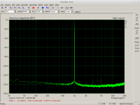
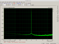
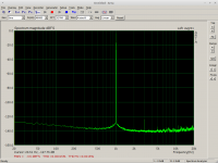
Unfortunately in my card the left channel distorts a bit more than the right one, as seen on the screenshots. How about the difference in the compensated channels?
Screenshots:
1) Right channel - plain hardware
2) Left channel - plain hardware
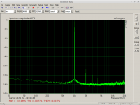
3) Right channel - compensated
4) Left channel - compensated
Unfortunately in my card the left channel distorts a bit more than the right one, as seen on the screenshots. How about the difference in the compensated channels?
Screenshots:
1) Right channel - plain hardware
2) Left channel - plain hardware
3) Right channel - compensated
4) Left channel - compensated
Attachments

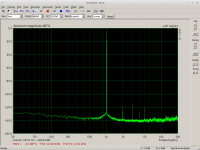
Wow, excellent results. Your topology can decrease distortion, though your soundcard already has low harmonics even in before calibration. I guess your ESI juli has pcm179X because the slight increase of noise power in LF is similar to my pcm1792 but I can't have such performance out of pcm1792.
pic 3) and 4) are probably the best numbers by a standard soundcard. Your algorithm is a convenient way to have a good oscillator. The only disadvantage is you need accurate reference one for the calibration. Are there harmonics hike after all if you change frequency even if the coefficients are the same value?
pic 3) and 4) are probably the best numbers by a standard soundcard. Your algorithm is a convenient way to have a good oscillator. The only disadvantage is you need accurate reference one for the calibration. Are there harmonics hike after all if you change frequency even if the coefficients are the same value?
Thanks
Juli uses DAC AKM AK4358 and ADC AK5385. In my setup it is in a shielded enclosure, connected via PCI extension cable Headless Amplifier Measurement Workstation .
When drifting from the calibration frequency the compensation gradually deteriorates but there are no ugly "spikes" generated by the cal polynom. I will make and post more measurements how the same calibration polynomial behaves for different frequency and levels.
I tested extending the polynomial with third-root component (using nonlin_curvefit() with custom function instead of polyfit() ). The determined coeffs were 100% consistent with polynom-only coeffs:
It did work to fight the third harmonics a bit better than pure polynomial, but higher-order harmonics appeared. IMO this is caused by the "rogue" behaviour of third-root around zero - high slope/first derivative . As a matter of fact, I think the compensation function should not contain any "unwieldy" functions/operations to be stable and safe. IMO polynomial just fits this requirement perfectly.
Juli uses DAC AKM AK4358 and ADC AK5385. In my setup it is in a shielded enclosure, connected via PCI extension cable Headless Amplifier Measurement Workstation .
When drifting from the calibration frequency the compensation gradually deteriorates but there are no ugly "spikes" generated by the cal polynom. I will make and post more measurements how the same calibration polynomial behaves for different frequency and levels.
I tested extending the polynomial with third-root component (using nonlin_curvefit() with custom function instead of polyfit() ). The determined coeffs were 100% consistent with polynom-only coeffs:
Code:
           polynomial    polynomial + 3rd root
3rd root   0.0000e+00   2.4238e-05
p0        -4.5126e-06  -4.5126e-06
p1         9.9327e-01   9.9326e-01
p2         1.4912e-05   1.4912e-05
p3         4.3666e-05   1.7976e-06
p4         1.4950e-05   1.4950e-05
p5        -5.4140e-05  -1.7159e-05
It did work to fight the third harmonics a bit better than pure polynomial, but higher-order harmonics appeared. IMO this is caused by the "rogue" behaviour of third-root around zero - high slope/first derivative . As a matter of fact, I think the compensation function should not contain any "unwieldy" functions/operations to be stable and safe. IMO polynomial just fits this requirement perfectly.
Attachments
The results are really impressive. have you inserted something with known distortion in the chain to see if it reports correctly? Looking at this differently you could measure with and without and determine the error curve of a DUT which could suggest fixes?
Is the process manual? I have a system with 3 different "pro" soundcards I could bring up with Ubuntu and give you remote access if that would help. And some very low distortion analog sources.
Is the process manual? I have a system with 3 different "pro" soundcards I could bring up with Ubuntu and give you remote access if that would help. And some very low distortion analog sources.
IMO polynomial just fits this requirement perfectly.
Well,
my beef question is how the ESS & internal THD registers (Levels and may other coeff's) had to be configured.
While I did not find any public even on a single mentioned paper and the expected results. Or is this dead fish?
IMHO this behaves not linear by signal level nor signal frequency & limited to 1..3 THD's! Even by temperature, stray/wide chip accuracy and connected gear. Even careful of connected HW's & even THD given from the cables.
In other words the polynom's will be different for each chip DAC / ADC too.
While on late experiences, compensations can be done with related HW & SW to a very deep degree.
Hp
have you inserted something with known distortion in the chain to see if it reports correctly?
Not yet in real measurement, only theoretically in octave. This post is in czech but the listings are in english - recovery of -120dB distortion generated with chebyshev polynom hifi.slovanet.sk :: Zobrazi? t?mu - Softwarov? kompenzace harmonick?ho zkreslen? m??ic? smy?ky On top of my todo list once I get an hour free at home
Looking at this differently you could measure with and without and determine the error curve of a DUT which could suggest fixes?
Interesting idea, I did not think of it this way. Yes, it could work. It would not be exact since we do not know which part of the closed-loop compensation polynomial belongs to outputs and which to inputs. Yet sth like this could work:
Code:
OverallPol = conv(ClosedLoopPol, DUTPol)

DUTPol = deconv(OverallPol, ClosedLoopPol)
Is the process manual?
It is still very rudimental, I am still trying to find a better approximation than a poly. But I think I will move on to make a proper script people could test.
I have a system with 3 different "pro" soundcards I could bring up with Ubuntu and give you remote access if that would help. And some very low distortion analog sources.
I appreciate your kind offer. The real-world trial requires recompiling alsa route plugin - I have a pcm_route.c version for ubuntu 14.04 and 16.04. Many changes in alsa-lib in recent years, the patch must be rebased for each version to allow compilation of alsa-lib in the distribution version.
If you recorded 5 secs of clean closed-loop stereo data 1kHz -1dB gain 24/32bits generated by sox, for each card, I would do the analysis remotely offline just to test detection and recovery in my script and post the results here afterwards. It would be a great help, thanks.
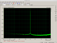
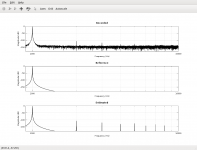
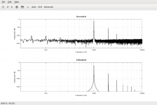
Recovery of a distortion below native resolution:
Since I have no analog distortion available, I simulated the distortion on the digital output side.
This transfer polynom generates approx. -130dB on second harmonic:
I entered this polynom into output device definition of .asoundrc.
Screenshots:
1) Native HW resolution
2) Compensated, no distortion (output device hw:Juli in Arta)
3) Distorted -130dB second harmonic (the distorting output device in Arta)
The third harmonic did not change, second harmonic clearly shows the -130dB distortion now.
Since I have no analog distortion available, I simulated the distortion on the digital output side.
This transfer polynom generates approx. -130dB on second harmonic:
Code:
distortpoly = leftpadz(db2mag(1) * chebyshevpoly(1,1) );
distortpoly += leftpadz( db2mag(-130) * chebyshevpoly(1,2));

-3.1623e-07   1.0000e+00   6.3246e-07
I entered this polynom into output device definition of .asoundrc.
Screenshots:
1) Native HW resolution
2) Compensated, no distortion (output device hw:Juli in Arta)
3) Distorted -130dB second harmonic (the distorting output device in Arta)
The third harmonic did not change, second harmonic clearly shows the -130dB distortion now.
Attachments
Last edited:
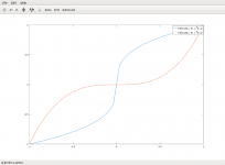
If we could find an inverse "function" to any forward transfer polynomial, all the harmonics would be gone. Unfortunately a general polynomial has no inverse function, only in specific cases. We would need a "clever" algorithm instead.
Examples of measured forward transfer polynomials we need to inverse:
These polynomials define the static distortion of the measurement loop. We need to compensate for them. My code does it by finding an inverse polynomial to the transfer one by least-squares fitting. Unfortunately that is just an approximation which has its limits...
There must be and is a way...
Examples of measured forward transfer polynomials we need to inverse:
Code:
4.67564455734586e-06   1.00653508892274e+00  -1.99155893092351e-05  -6.49608887946560e-06   4.93538141860459e-05  -1.45018372290258e-04   3.34620276711483e-04   2.76798196853043e-04  -2.71192108780933e-04

1.68540877936706e-03 9.58837554689159e-01 -2.67138889410604e-02 -1.96365494839931e-03 -2.92342237803849e-03 -9.37151472477120e-03 4.30382427551057e-02 5.35131390522822e-02 -1.93274826271800e-01There must be and is a way...
Attachments
Marcel, thanks a lot for suggestion. I am just afraid we are dealing with such small numbers that any omission creates a visible error.
In the end I decided to try the hard-force approach - a lookup table, i.e. reverse index/value mapping of values calculated by the forward polynom for the whole int24 range. On my i5 notebook octave calculates the complete reverse lookup vector for the forward polynom with 16 mil. values in under two seconds. Hopefully tomorrow I will fix all the incorrect-boundary bugs and test the approach.
In the end I decided to try the hard-force approach - a lookup table, i.e. reverse index/value mapping of values calculated by the forward polynom for the whole int24 range. On my i5 notebook octave calculates the complete reverse lookup vector for the forward polynom with 16 mil. values in under two seconds. Hopefully tomorrow I will fix all the incorrect-boundary bugs and test the approach.
Last edited:
- Home
- Design & Build
- Equipment & Tools
- Digital Distortion Compensation for Measurement Setup