Sorry if this is in the wrong place, but I'm looking for info on making a simple sine wave oscillator for LF. 0 to 100Hz would be fine. I've read about doing it with opamps, but how hard would it be to do it with a triode? So far, I've only built amplifiers. I'm pretty good at making them NOT oscillate 
Cheers
Koda
Cheers
Koda
I'm looking for info on making a simple sine wave oscillator for LF. 0 to 100Hz would be fine.
Check some old tube HP oscillator schematics for ideas, but so low in frequency is difficult.
Sorry if this is in the wrong place, but I'm looking for info on making a simple sine wave oscillator for LF. 0 to 100Hz would be fine. I've read about doing it with opamps, but how hard would it be to do it with a triode? So far, I've only built amplifiers. I'm pretty good at making them NOT oscillate
Cheers
Koda
Ideas can be had on Heathkit IG-72, no triodes.. Due to AC coupling, Osc. section timing parts, and other time constants even <10 Hz is difficult, plus the distortion spec degrades rapidly.
Their earlier generators maybe easier on tubes but uses more rare hardware Eg ganged capacitor tuning for continuous tuning (within each band).
Going low would require a digital design DDS etc.
Last edited:
I've read about doing it with opamps, but how hard would it be to do it with a triode?
If you really do need such extreme VLF, it's best to go ss.
My old HP3311A does great LF, and used ones are cheap.
HP 3311A FUNCTION GENERATOR 0.1Hz-1MHz WORKING with Warranty | eBay
Last edited:
Not sure if you're looking for a quick design fait accompli or want to learn enough to design your own.
If into study then Pete Millett's Tubebooks site has several books with good sections on oscillators, possibly the most quickly useful being in Seely's Electron Tube Circuits (Starting on P244) , but there are also others by Reich, Edson, or Gernsbach .
HTH
If into study then Pete Millett's Tubebooks site has several books with good sections on oscillators, possibly the most quickly useful being in Seely's Electron Tube Circuits (Starting on P244) , but there are also others by Reich, Edson, or Gernsbach .
HTH
 Moved to Equipment & Tools.
...a simple sine wave oscillator for LF. 0 to 100Hz would be fine....
Steal Fender's tremolo oscillator. Scale the caps as needed.
Drawback: as implemented, F scales as third-root of change of R. We generally can not change R even 10:1 without killing gain and stalling. This gives only an octave of range. A dual-gang pot gets you 2+ octaves. (A dual-gang in a Wien scales F directly with R so 10:1 is easy; but generally needs a 2-stage amplifier.)
What is "zero frequency"?? Once a day? Once a month? 20Hz? Put a number on that. 20Hz is easy. The (solid state) Heath oscillators would tune below 1Hz (but lamp stabilization gets wonky). "Minutes" would strongly suggest digital synthesis (some CMOS and a handful of resistors).
Going low would require a digital design DDS etc.
As Infinia and PRR both said, very low frequencies (much lower than 10 Hz) are very difficult to generate with analog electronics, and you need a digital approach instead."Minutes" would strongly suggest digital synthesis (some CMOS and a handful of resistors).
If you're willing to tinker with digital hardware and software, there is an interesting (but not dirt-cheap) option:
1) SparkFun MiniGen - Pro Mini Signal Generator Shield - BOB-11420 - SparkFun Electronics
2) Datasheet: https://cdn.sparkfun.com/datasheets/BreakoutBoards/AD9837.PDF
3) Software: GitHub - sparkfun/MiniGen at V_H1.0_L1.1.0
I haven't worked with this device (though I plan to), but as I understand it, you basically send the appropriate (digital) numbers to the MiniGen board, usually using an Arduino microprocessor board, and the MiniGen then spits out a sinewave at the corresponding frequency. The datasheet says you can get down to 0.06 Hz, roughly one cycle every 17 seconds.
The output of the MiniGen is DC-coupled (a really good idea when you get down to 0.06 Hz!), and has a DC offset on it (half the power supply voltage.) If you need that DC offset removed, you probably need to follow it with an opamp stage designed to subtract the offset and provide an offset adjustment trim control.
If what you really want is, say, 10 Hz - 100 Hz, and you don't need extraordinarily low distortion, then what you want can be done with a TL072 or two and a handful of other components. One interesting approach is on Rod Elliott's website (you would probably want to increase VR1 to reach those low frequencies): http://sound.whsites.net/project86.htm
The traditional Wien-Bridge approach is simpler on paper, but it's quite hard to stabilize it's amplitude at very low frequencies, without also generating huge amounts of distortion at the same time, as well as a tendency for the oscillator to take a very long time to settle down. (The output tends to "bounce" for quite a while after any change to frequency.) The approach discussed in that Rod Elliott project doesn't suffer from those problems.
-Gnobuddy
1) forget tubes.
2) forget phase shift oscillators: to change frequency you need to vary *3* resistors simultaneously. Good luck with that.
In fact, good luck in finding a triple ganged pot.
Did I say they distort a lot too? Your sinewave will clearly clip on one side, sometimes maybe on both but assymmetrically
3) XR2206 is not a sinewave oscillator by any means but a square/triangle wave function generator, where the triangle is bent by a diode matrix to resemble a sinewave.
4) check what established Lab Oscillators do: a gain stage which is *easily* made out of Op Amps, old ones might have used a discrete Op Amp but function is the same, with frequency setting/tuning built around a Wien bridge, which is the most stable RC based one, and easily allowing a 20:1 tuning range
We are talking an Analog solution , of course, which is implied by your possible interest in a Tube circuit.
Thank you all for the replies. Yes, I already have a DDS, I was just wanting to experiment with oscillation. The desire for 0-100Hz really translates into making an LFO for music synth purposes with the ability to scale it to higher frequencies, and the desire to use tubes is mainly because I understand them. I know how to make a Square wave oscillator with a 555 though.
Steal Fender's tremolo oscillator. Scale the caps as needed.
What is "zero frequency"?? Once a day? Once a month? 20Hz? Put a number on that. 20Hz is easy. The (solid state) Heath oscillators would tune below 1Hz (but lamp stabilization gets wonky). "Minutes" would strongly suggest digital synthesis (some CMOS and a handful of resistors).
In this case 0 would be no oscillation (AKA off) while adjusting a resistance would gradually increase the frequency to say 20Hz, then a range switch could be used for 20Hz and up.
In a 555 oscillator, the voltage across the timing capacitor is a (crude) triangle wave. It's crude because the "sides" of the triangle are not quite straight, but rather, are sections of an exponentially rising / falling voltage....making an LFO for music synth purposes...
<snip>
I know how to make a Square wave oscillator with a 555 though.
If you buffer that signal with an opamp or JFET, you can potentially use that triangle wave as your LFO voltage.
555 timers are also quite good at generating quite low frequencies. With a reasonably big capacitor and resistor, it is quite easy to generate time delays of minutes, so you can get frequencies more than low enough for any practical LFO synth use.
If you need a fairly decent sine wave (rather than a crude triangle), that is also do-able with a 555 timer, and a little extra circuitry. First you replace the timing resistor with a constant current source in the 555 oscillator. This makes the capacitor waveform a true triangle with straight sides.
Then you feed that triangle into a shaping circuit that rounds off the corners, and makes it into an approximate sine wave. For LFO purposes, you don't need a very low distortion sine wave, so something as simple as a buffer opamp and a pair of LEDs in reverse-parallel can be used to round off the triangle wave and turn it into an approximate sine. This will give you a "sine" with a few percent distortion, which is as good as you will get from a typical tube vibrato oscillator, etc.
Hewlett-Packard built their company on the foundation of their excellent audio frequency Wien Bridge oscillator, but times have changed, and it is hard to build a good low-distortion Wien Bridge oscillator these days ( more on this here: http://sound.whsites.net/project22.htm )
Elliott's design uses a tungsten-filament lamp to stabilize amplitude, which works acceptably at audio frequencies, but not very well at the LFO frequencies you want.
One very important question: does your LFO need to behave well when the frequency is changed? If you are planning to change LFO frequency in mid-song, for example, a Wien Bridge oscillator is a very bad choice, as it will sometimes stop oscillating all together after a sudden frequency change, and always takes time to "settle" down to steady oscillation again.
This same problem applies to guitar-amp tremolo oscillators too.
The 555-triangle-shaped-to-sine approach will not have these problems.
You can also do the triangle-shaped-to-sine thing with a couple of opamps rather than a 555. Opamps are slow at switching, but at LFO frequencies, that won't matter.
-Gnobuddy
The trouble is the yawning gap between 0 Hz and any actual AC frequency. Think about the usual log-log frequency plot: where is 0 on the x-axis? (It's at -infinity!)In this case 0 would be no oscillation (AKA off) while adjusting a resistance would gradually increase the frequency to say 20Hz, then a range switch could be used for 20Hz and up.
This means 0.01 Hz is infinitely far away from 0 Hz as far as an oscillator is concerned (you need an infinite resistance to oscillate at 0 Hz).
It also means the band from 0.01 Hz to 0.1 Hz is just as big a range as the band from 20 Hz - 200 Hz. Both are 1:10 frequency ratios, and occupy the same horizontal width on a usual log-log plot.
In other words, it is impossible to make an oscillator that goes smoothly from 0 Hz to 20 Hz. It is possible to make an oscillator that goes smoothly from 0.01 Hz to 0.1 Hz, or 1 Hz to 10 Hz, or similar.
So, for people to be able to give you a helpful answer, we really do need a finite, non-zero, lowest desired frequency of oscillation. When the oscillator is switched on (and not off), what is the lowest frequency you wish it to oscillate at? 1 Hz? 0.1 Hz? 0.01 Hz?
Keep in mind, each additional decade of frequency range adds just as much complexity as any other decade. If you're unlikely to need frequencies below, say, 1Hz, drop them from the specification. That will make the design much less complex.
-Gnobuddy
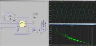
Here's an LTSpice simulation of an oscillator that uses a 555 timer to generate an (approximately) sine LF signal, set to about 1 Hz in this simulation.
The JFET, along with R1, acts as a constant current source, so we get a nice triangle from the 555. Varying R1 changes the amount of current, and so changes the frequency. A smaller value of R1 will raise the frequency.
One opamp buffers the triangle, the second uses a pair of back-to-back LEDs to shape it into something close to a sinewave.
The FFT shows that the harmonics are around 40 dB down from the main peak, so there really isn't that much distortion, at least for synth LFO purposes.
This is not a complete design, just a quick proof of concept circuit I threw together to see what would happen.
-Gnobuddy
Attachments
- Home
- Design & Build
- Equipment & Tools
- Sine wave oscillator