Sometimes you can even try to turn off the *helicopter*Thankfully, you can turn off the oscillator")
By sheer accident, I stumbled across a very clever method of shaping a triangle wave into a remarkably good sine wave. The method uses the nonlinear Id/Vds characteristic of a JFET to do the shaping.
Apparently this method was used in vintage analogue synths, though I have never seen it in any of the dozens of electronics books I've read over the decades.
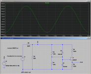
The attached LTSpice screenshot shows the plan. The actual shaping circuit consists of the 2N5457 JFET, along with four resistors and two small-signal diodes.
The voltage source generates triangle waves at 500 Hz, adjusted by R5/R6 to about 4 volts peak to peak. I adjusted the exact amplitude by trial and error to produce the lowest distortion sinewave.
The output signal is taken from the source of the JFET, and is about 500 mV peak to peak.
Not surprisingly given the 100 ohm source and drain resistors, it takes about 5 mA peak to peak of current through the JFET to generate the 500 mVpp output signal.
In principle the circuit will work with any symmetrical JFET (source and drain are interchangeable.) In my simulations, however, some JFETs need an alarming amount of current and voltage to generate a sine.
To avoid these issues, a JFET with fairly low pinch-off voltage (Vp) and fairly high channel resistance at Vgs=0 is what is needed. The 2N5457 was still available at Mouser last time I checked, so I tried that in the simulation, and it worked well.
Note that the sine is only 500 mVpp, meaning you may need to amplify it before it is big enough for your purposes.
For minimum distortion, the circuit is very fussy about the exact amplitude of the incoming triangle wave, and also, to a lesser degree, the values of the source and drain resistors. A trimpot to set amplitude will be necessary.
When everything is tuned just right, though, this surprisingly simple circuit is also surprisingly good at shaping a triangle into a sine. LTSpice thinks THD is well under 1% in my simulation (under 0.1%, actually), and a few discussions I found online about this circuit suggest this might actually realistic, with reports of as little as 0.05% THD, though this is probably very hard to maintain in real-world conditions.
In my simulation, I tried overlaying a pure sine wave generator signal (the one built into LTSpice) onto the shaped triangle signal. The two traces fall almost perfectly on each other, overlapping for most of the cycle, with a few places here and there where they are a pixel apart on my computer screen. Quite remarkable, particularly since there is nothing inherently sinusoidal about a JFETs Id-Vds curve!
-Gnobuddy
Apparently this method was used in vintage analogue synths, though I have never seen it in any of the dozens of electronics books I've read over the decades.
The attached LTSpice screenshot shows the plan. The actual shaping circuit consists of the 2N5457 JFET, along with four resistors and two small-signal diodes.
The voltage source generates triangle waves at 500 Hz, adjusted by R5/R6 to about 4 volts peak to peak. I adjusted the exact amplitude by trial and error to produce the lowest distortion sinewave.
The output signal is taken from the source of the JFET, and is about 500 mV peak to peak.
Not surprisingly given the 100 ohm source and drain resistors, it takes about 5 mA peak to peak of current through the JFET to generate the 500 mVpp output signal.
In principle the circuit will work with any symmetrical JFET (source and drain are interchangeable.) In my simulations, however, some JFETs need an alarming amount of current and voltage to generate a sine.
To avoid these issues, a JFET with fairly low pinch-off voltage (Vp) and fairly high channel resistance at Vgs=0 is what is needed. The 2N5457 was still available at Mouser last time I checked, so I tried that in the simulation, and it worked well.
Note that the sine is only 500 mVpp, meaning you may need to amplify it before it is big enough for your purposes.
For minimum distortion, the circuit is very fussy about the exact amplitude of the incoming triangle wave, and also, to a lesser degree, the values of the source and drain resistors. A trimpot to set amplitude will be necessary.
When everything is tuned just right, though, this surprisingly simple circuit is also surprisingly good at shaping a triangle into a sine. LTSpice thinks THD is well under 1% in my simulation (under 0.1%, actually), and a few discussions I found online about this circuit suggest this might actually realistic, with reports of as little as 0.05% THD, though this is probably very hard to maintain in real-world conditions.
In my simulation, I tried overlaying a pure sine wave generator signal (the one built into LTSpice) onto the shaped triangle signal. The two traces fall almost perfectly on each other, overlapping for most of the cycle, with a few places here and there where they are a pixel apart on my computer screen. Quite remarkable, particularly since there is nothing inherently sinusoidal about a JFETs Id-Vds curve!
-Gnobuddy
Attachments
Funny thing a traffic reporter helicopter use to hover over my high school neighborhood for early morning reports. Well below FAA mandates. One morning I shot off a few model rockets. The pilot got the hint.
Now on topic the HP oscillator was an impressive step forward in design. It used a very high impedance circuit and a multi section tuning capacitor.
Hard to get the capacitors custom made today. So to use the same circuit with variable resistors and fixed capacitors would require values of 10 megohms or more. It also used a light bulb for gain stabilization. So I would try stacking three trim pots by carefully drilling a hole through the screwdriver adjustment slot and ganging them on a shaft. Range switching cane be done by changing the capacitor values.
A fairly husky light bulb designed for automotive tail lights could be used as a gain control. But I would look to something more modern like an LED and a CDS photocell. Even a pair of inverse parallel Zener diodes would work but at higher distortion and faster settling time.
So my suggestion would be to buy a ten dollar HP unit and rebuild it.
Last edited:
Here is another idea: it is based on the old concept of heterodyning (a basic building block of frequency synthetizers).
It sounds complicated, but it can be implemented reasonably simply:
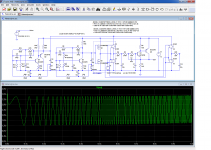
In this example, two oscillators are mixed (multiplied): one, built around Q4 is optimized for spectral purity whilst the other (Q3) is made (slightly) frequency-variable.
Other than this distinction, both are very similar, meaning they will track closely against temperature, supply, etc. variations.
The mixer is a section (1/3rd) of CD4053: in the sim, it is represented by a complicated mess of MOS transistors and ideal switches, but that's just to avoid a specific model, it works with native spice components.
The result is filtered by Q1, wired as a third order filter.
The nice thing about this scheme is that it inherits from the good sides of both the mixing parents, in particular the spectral purity of the sinusoidal one.
In the sim, R24 symbolizes the frequency control, which has been made variable from 0 to 1K over a period of 1 second (the total sim time).
The output frequency varies from some mHz to 200Hz.
The lowest actual frequency reachable depends mainly on two factors:
1)the relative frequency stability of the two oscillators
2)the pulling effect of one oscillator on the other. This effect is not visible here because the wobbulation hides it, but if you make R24 fixed, you will see a distortion of the output for extremely low frequencies.
The effect is combated by using a second 4053 wired in antiphase (S3, S4), but the compensation is not perfect, because the low-passed output is also antiphase, and only the LP input components are present.
If frequencies below 1Hz are of interest, an additional buffer transistor could be added after Q5.
Note that in its current form, the circuit achieves a 200:1 frequency ratio, with a constant and regulated amplitude (another advantage of heterodyne circuits), a good sinusoidal waveform and only 5 ordinary transistors, plus one common IC.
I made crude choices and assumptions for this summary example: I opted for a 400Hz LP (for a 200Hz bandwidth), ~10kHz carriers, but in reality, these choices could be optimized and better suited to the actual purpose of the circuit: maybe a 3kHz carrier frequency would be sufficient, etc.
In general, there is a tradeoff between purity, frequency span, lowest frequency, filter order and stability.
However, this example shows that it shouldn't be too difficult to reach decent values on all parameters without too much complication.
Needless to say that the oscillator's components need to be of a reasonably good quality, even if they are matched
It sounds complicated, but it can be implemented reasonably simply:
In this example, two oscillators are mixed (multiplied): one, built around Q4 is optimized for spectral purity whilst the other (Q3) is made (slightly) frequency-variable.
Other than this distinction, both are very similar, meaning they will track closely against temperature, supply, etc. variations.
The mixer is a section (1/3rd) of CD4053: in the sim, it is represented by a complicated mess of MOS transistors and ideal switches, but that's just to avoid a specific model, it works with native spice components.
The result is filtered by Q1, wired as a third order filter.
The nice thing about this scheme is that it inherits from the good sides of both the mixing parents, in particular the spectral purity of the sinusoidal one.
In the sim, R24 symbolizes the frequency control, which has been made variable from 0 to 1K over a period of 1 second (the total sim time).
The output frequency varies from some mHz to 200Hz.
The lowest actual frequency reachable depends mainly on two factors:
1)the relative frequency stability of the two oscillators
2)the pulling effect of one oscillator on the other. This effect is not visible here because the wobbulation hides it, but if you make R24 fixed, you will see a distortion of the output for extremely low frequencies.
The effect is combated by using a second 4053 wired in antiphase (S3, S4), but the compensation is not perfect, because the low-passed output is also antiphase, and only the LP input components are present.
If frequencies below 1Hz are of interest, an additional buffer transistor could be added after Q5.
Note that in its current form, the circuit achieves a 200:1 frequency ratio, with a constant and regulated amplitude (another advantage of heterodyne circuits), a good sinusoidal waveform and only 5 ordinary transistors, plus one common IC.
I made crude choices and assumptions for this summary example: I opted for a 400Hz LP (for a 200Hz bandwidth), ~10kHz carriers, but in reality, these choices could be optimized and better suited to the actual purpose of the circuit: maybe a 3kHz carrier frequency would be sufficient, etc.
In general, there is a tradeoff between purity, frequency span, lowest frequency, filter order and stability.
However, this example shows that it shouldn't be too difficult to reach decent values on all parameters without too much complication.
Needless to say that the oscillator's components need to be of a reasonably good quality, even if they are matched
Attachments
FYI, interfering with the safety of aircraft is now considered a felony and a terrorist act. Please, nobody even think about doing anything like this. Shining an ordinary laser pointer at a helicopter is enough to get you a felony charge and a long jail sentence....traffic reporter helicopter...one morning I shot off a few model rockets...pilot got the hint
OP wants to get down to 0.5 Hz, or a 2-second period. Lacking a thermal time constant of tens of seconds, light bulb stabilization would cause considerable harmonic distortion....used a light bulb for gain stabilization...
If you do manage a time constant of tens of seconds, then the settling time after each frequency change is very long.
That would require a lot of power driven into it to heat it up enough to change the filament resistance.A fairly husky light bulb designed for automotive tail lights could be used as a gain control.
-Gnobuddy
Gno,
Helicopter was operating so low the pilot would have been in trouble, 12 year old kids are minors and not many charges stick!
As to light bulbs it requires very little relative power to use the positive thermal characteristics when the fixed gain is close. So a thick filament lamp works.
As to the heterodyne method that was used by Bruel and Kjaer in the past.
There are many details on both light bulbs and stabilization methods on this thread: Low-distortion Audio-range Oscillator One contributor used DC to change the resistance of the lamp to control the loop gain. Its was very trick and low distortion but had drawbacks. The best solution I think was using an ADC + multiplying DAC as a sample and hold. Turns out to not be so difficult to implement.
GR originated the bfo as a low distortion source. A bit too complicated for what you get today. I think Rohde and Schwartz also used it in one of their oscillators.
GR originated the bfo as a low distortion source. A bit too complicated for what you get today. I think Rohde and Schwartz also used it in one of their oscillators.
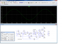
Another possibility is to use a SVF as an oscillator, and take advantage of the alternative mode of frequency control it makes possible:
Instead of directly varying the timing components, one can act on the gain in front of each integrator.
This means no awkward component values, a good stability because the potentiometer is actually used as such, and not as a variable resistance.
The tracking between the two pots is also completely irrelevant, to the extent that one section can be omitted completely (with the range reduced to its square root, of course).
Very wide spans and very low frequencies are possible: in this example, the pots are set to 1/50, yielding a frequency of 0.3Hz (the top frequency is 15Hz).
Of course, low settings are demanding for the opamps, in particular their OLG, but since the frequency is minimal in these conditions, the OLG is at its best.
With modern opamps, this should not be a problem, especially at VLF.
With log pots, it would be practical to cover a 1:100 ratio (or even more) in a single range
Attachments
Even in sim it required a compensation switch + network, but in reality you would also need to care about capacitive and inductive proximity coupling, and the supplies would need extra care.I wouldn't have thought you could prevent the two oscillators from locking to each other when they are tuned only 0.5 Hz apart
At a carrier frequency of 10kHz, it is still a relatively easy job provided you are aware of potential pitfalls from the start.
The quality is that of the "clean" reference waveform, further tidied up because the other mixing waveform is a squarewave, which only has odd order harmonics, decreasing in direct proportion with their rank., or that you could get a good quality sine out of the mixer.
When the frequencies become really close, mutual injection causes a phase comparator behavior which degrades the output waveform.
Rectifying and filtering the output of the oscillator to make a (nearly) DC control voltage is/was routinely used with the LED/LDR and JFET stabilization methods. But adding the extra poles in the servo feedback loop tends to make settling times long, and/or lead to outright servo oscillation, with the LFO producing amplitude-modulated output, or short bursts of sinewaves with dead silence in between!One contributor used DC to change the resistance of the lamp to control the loop gain.
One of the approaches suggested in this thread was to use a 3RC oscillator with a six-phase rectifier. With so many phases, what comes out of the rectifier requires only light filtering to become almost pure DC. So it is still capable of the fairly rapid changes needed to make a stable servo loop, so the LFO output has a reasonably fast settling time.
Personally, I think Rod Elliott's "miniosc" is an excellent solution for the purposes of this thread. It's relatively simple, distortion is far lower than necessary for this application, and Mr. Elliott has been nice enough to provide a proven schematic that only needs to be tweaked slightly to lower the frequency range: Miniature Audio Oscillator
OP didn't want to go digital, otherwise there are inexpensive DDS chips and modules that will generate a decent sine for you. The cheapest modules come from Hong Kong vendors, but there are $30 versions marketed by North American vendors, such as this Sparkfun module: SparkFun MiniGen - Pro Mini Signal Generator Shield - BOB-11420 - SparkFun Electronics
-Gnobuddy
Perhaps the simplest solution is the ancient Intersil ICL8038, sort of a function generator on a chip. I used this really nice part circa 1978. A few trim pots tweak distortion to about 1%. It's also a VCO, easily tuned to very low frequencies. I was surprised to find they're readily available on Ebay, etc, for well under $5.
https://www.intersil.com/content/dam/Intersil/documents/icl8/icl8038.pdf
Cheers.
https://www.intersil.com/content/dam/Intersil/documents/icl8/icl8038.pdf
Cheers.
I have one of these:Perhaps the simplest solution is the ancient Intersil ICL8038, sort of a function generator on a chip. I used this really nice part circa 1978. A few trim pots tweak distortion to about 1%. It's also a VCO, easily tuned to very low frequencies. I was surprised to find they're readily available on Ebay, etc, for well under $5.
https://www.intersil.com/content/dam/Intersil/documents/icl8/icl8038.pdf
Cheers.
http://www.sinometer.com/uploadImage/2012-09-27/2012092714544811255546.jpg
It is a 8038 with an attendent micro-controller
"...can you do it with a triode....?
THE TYPE 1304-B BEAT-FREQUENCY AUDIO GENERATOR
https://www.ietlabs.com/pdf/GR_Experimenters/1954/GenRad_Experimenter_June_1954.pdf
http://jptronics.org/GR/GR1304B/GR1304B.pdf
Brüel & Kjær: Beat Frequency Oscillator
Beat Frequency Oscillator 1022 Equipment Bruel & Kjaer; Naerum
RCA had one long before but I don't find those plans (few were made).
A Theremin is a BFO, tuned by hand-wave instead of knob.
Last edited:
And diyAudio is severely lacking in threads about theremins, particularly ones with the rich timbre that Lev Termen coaxed out of his instruments.A Theremin is a BFO, tuned by hand-wave instead of knob.
I have a friend who is held back from playing musical instruments by various physical ailments, but I suspect a theremin might be an option - zero impact, no grip strength required, and you don't have to play lots of notes per second.
For the sake of the sanity of potential listeners, I think a theremin with audio pitch that can be optionally quantized to the chromatic scale would be a Very Good Thing (TM). After all, in nearly a hundred years, no one but Clara Rockmore seems to have demonstrated the ability to play a theremin with truly perfect pitch control.
Pitch quantization would eliminate the theremin's most noteworthy musical characteristic (perfectly smooth glissandos), but also eliminate the theremin's most obnoxious musical characteristic (it's always horribly off-pitch, unless Clara Rockmore is playing it.)
Okay, Clara Rockmore or Katica Illényi. Both formidably talented violin prodigies, not coincidentally.
-Gnobuddy
A multiphase oscillator should be possible with a conventional two-ganged pot. Use the dual integrator approach (that needs 2x integrators and an inverter) using 3 IC's (or two dual op amps). Wire the last stage (inverter) with a gain of just over 1 and a trimmer LDR.
Use a fourth IC to invert the signal from the first, that gives you four phases. Use diode-rectifiers from each phase (if distortion is not too big an issue) to feed a fifth IC which should generate a signal based on the DC average of the four phases and needs a relatively small capacitor to filter the signal. Use the output to contol an LED and that should be done.
SOrry can't look into this further at present, maybe after other priorities ...
I was at a ballet performance in Berkeley a few weeks ago where a Theremin was a key part of the live music. The performance was impressive and worked with the dancing. however I could see where the performers arms might be really tired afterwards.
The multiphase version has been explored and documented, complete with an 8 phase variant here. Personally I would still prefer the sample and hold with its potentially faster settling and lower ripple once you start getting the complexity up.
The multiphase version has been explored and documented, complete with an 8 phase variant here. Personally I would still prefer the sample and hold with its potentially faster settling and lower ripple once you start getting the complexity up.
... oscillator .... with a triode?...
Vacuum Tube Oscillators, William A. Edson, 1953 http://mirror.thelifeofkenneth.com/...be_Oscillators_William_A._Edson_1953_text.pdf
- Home
- Design & Build
- Equipment & Tools
- Sine wave oscillator