Sorry if this is in the wrong place, but I'm looking for info on making a simple sine wave oscillator for LF.
If low distortion (<0.0001 %) would be a requirement, an approach could be a crystal oscillator followed by a crystal filter. The pure, for instance 1 MHz sine wave is fed to a sample hold circuit with low distortion (Analog Devices) and the sample frequency made variable, from for instance 1000...1100 KHz. The output of the sample hold via a low pass filter and you have a low distortion sine generator from 0 to 100 KHz without the hassle and dazzle of (slow!) feedback loops (lamps, LDR etc.) for amplitude control.
The 555 has stayed in production since 1972 because it is so incredibly versatile, and can be made to do so many things that the chip designer never anticipated.Interesting circuit.
So when you said you had used a 555 to make a square wave, that got me curious as to whether I could coax a 555 timer to also make a sine wave. Apparently the answer is "Yes!"
")
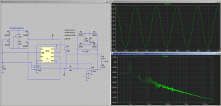
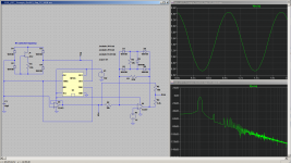
I tinkered with my circuit simulation a little more, and in exchange for a little bit more complexity in the sine-shaping network, I managed to make it produce a considerably nicer-looking sinewave signal.
Traditionally, shaping a triangle into a sine often suffers from several of these problems: (a)The "sine" has abnormally straight sides, (b) There are sharp "kinks" in the waveform, and (c) The tips are "pointy" and not smoothly rounded.
The 5-diode shaper is my own idea. Using R5/R4 to subtract off the "pointy" tips of the sine wave is an idea I found on the Internet. Between the two, the sine is really quite nice, at least in the LTSpice simulation! Nice and curvy along the entire cycle, with no sharp kinks or points anywhere to be seen.
They made entire digital computers with triodes, so why not?I wonder how hard it would be to make a 555 with triodes
-Gnobuddy
Attachments
Last edited:
I designed a three-phase oscillator with a frequency range of 1Hz-30kHz for audio testing. I used three 10k pots with feed-thru holes and my custom spindle to adjust them at the same time. Works well. Distortion is very low (less than my measurement capability which limits at around .003%.) Uses several op-amps and an LED/LDR amplitude stabilisation scheme. The only restriction on LF is the rather large caps needed - in this case 22uF. They should not be electrolytic as those have a polarity requirement and poor tolerances.
There are companies who will assemble multi-gang pots if you search. You do not need pots if a switched resistor network will be OK. I recommend this type over a Wein Bridge. Although a WB only needs dual gang pots, amplitude stabilisation is tricky (the old favourite thermistor is obsolete; lamps don't work well at LF as they create 3rd H distortion; both of these also cause "bounce" for several cycles; and LED/LDR needs to be driven from sample and hold, where a suitable trigger signal is not available. An alternative to WB is a quadrature (look this up) where you can derive a sample and hold trigger signal from the 90 degrees signal.
I prefer analog, obviously, but if I were to do a digital I would just program a 12 or 16 bit sinewave lookup table in an EEPROM and drive the addresses from a counter, and send the output into a DAC. You could use your multivibrator or 55 timer to control the clock (to the counter) frequency hence sinewave frequency. WOuld need filtering on the output I would think. No pots (except perhaps a single timer control) needed.
Last edited:
Ultra low frequency analog generators usually are built like functional (triangle) generators with sine convertor-filter (with quite high sine distortion), like Gnobuddy showed. I have Г6-27 functional generator (USSR, 1980-s), it starts from 0.001 Hz (and goes to 1 MHz). And it has triangle generator and sine convertor. It sine distortion is about 1-3 %.
Last edited:
Very cool! Presumably, this would also work using AD712 instead of TL072? I'll I'm missing is the JFET... I have some DN2540 but I doubt that would work here.The 555 has stayed in production since 1972 because it is so incredibly versatile, and can be made to do so many things that the chip designer never anticipated.
So when you said you had used a 555 to make a square wave, that got me curious as to whether I could coax a 555 timer to also make a sine wave. Apparently the answer is "Yes!"
I tinkered with my circuit simulation a little more, and in exchange for a little bit more complexity in the sine-shaping network, I managed to make it produce a considerably nicer-looking sinewave signal.
Traditionally, shaping a triangle into a sine often suffers from several of these problems: (a)The "sine" has abnormally straight sides, (b) There are sharp "kinks" in the waveform, and (c) The tips are "pointy" and not smoothly rounded.
The 5-diode shaper is my own idea. Using R5/R4 to subtract off the "pointy" tips of the sine wave is an idea I found on the Internet. Between the two, the sine is really quite nice, at least in the LTSpice simulation! Nice and curvy along the entire cycle, with no sharp kinks or points anywhere to be seen.
They made entire digital computers with triodes, so why not?
-Gnobuddy
I prefer analog, obviously, but if I were to do a digital I would just program a 12 or 16 bit sinewave lookup table in an EEPROM and drive the addresses from a counter, and send the output into a DAC. You could use your multivibrator or 55 timer to control the clock (to the counter) frequency hence sinewave frequency. WOuld need filtering on the output I would think. No pots (except perhaps a single timer control) needed.
If I went digital, I'd probably just use a microcontroller
As far as using a tube, it looks like the phase oscillator is the easiest to implement. If anyone has any info on old tube analog synth circuitry etc, It would be appreciated.Well, I'd probably use the microcontroller to control the clock frequency of the look-up table using a separate (also hardware) timer so the micro does not have to do much work, then it can be used for other things too, like displaying the frequency...If I went digital, I'd probably just use a microcontroller
See post #11, which is the same idea taken a little further. A dedicated DDS synthesis chip guarantees good waveforms, and all the micro has to do is tell it what frequency to generate....separate (also hardware) timer so the micro does not have to do much work, then it can be used for other things too, like displaying the frequency...
Other than that, the micro is free to drive LCDs, read pushbuttons to set frequency, or talk to a computer. I would think a computer-controlled LFO might open up some interesting musical possibilities.
-Gnobuddy
FET input and, if possible, low offset voltage...that's really all we need from the opamps. So I'm sure there are plenty of suitable opamps out there.Very cool! Presumably, this would also work using AD712 instead of TL072? I'll I'm missing is the JFET... I have some DN2540 but I doubt that would work here.
As for the DN2540, it might work, as it's a depletion-mode FET. I do have some concerns about how much drain-source voltage it needs for the curves to flatten out and behave like a good constant-current source. Worst case, there is only 1/3 Vcc across the (JFET + 2 Si diodes + 555 output devices).
So 5V to start with, then the two diodes drop 1.2V, the 555 output stage might drop a volt, leaving less than 3V across the JFET. Will that be enough? It's a little hard to tell from the datasheet curves, but I think at the rather low currents this circuit wants, it will be okay.
Are you okay with an oscillator that might take a minute to start-up (not heater warmup time, time for the oscillations to build up and stabilize)? Are you okay with an oscillator that stops and thinks for several seconds every time you change the frequency?As far as using a tube, it looks like the phase oscillator is the easiest to implement.
If the answer to both questions is "Yes!", then a three-RC phase shift oscillator might work for you.
I know nothing about this, but I know of someone who does: Tubelab_Com (George). He's mentioned working on a tube-based synthesizer a few times on diyAudio.If anyone has any info on old tube analog synth circuitry etc, It would be appreciated.
Mebbe send him a PM and ask if he has suggestions for you?
-Gnobuddy
Are you okay with an oscillator that might take a minute to start-up (not heater warmup time, time for the oscillations to build up and stabilize)? Are you okay with an oscillator that stops and thinks for several seconds every time you change the frequency?
Maybe I should have made it clearer that the three-phase oscillator stabilises in about 1 cycle. Even at 1Hz. It has no bounce as such, but does show a slight overshoot (maybe 10%) in changing frequencies. I agree that thermistor and lamp stabilised oscillators took several cycles to stabilise, but not a multiphase design, which is why these are preferable.
The key to this is that the feedback is actually fast. You use all three phases (separately buffered) to provide a six-phase rectified signal so that the control loop filter does not need to do much filtering. Hence quick and very little ripple, hence low distortion.
The slow speed of the LDR helps at higher frequencies as it acts as a second filter!
Another factor in the stability is that with three RC networks the capacitors tend to filter sudden changes, which is why overshoot is minimised.
Last edited:
We have a little bit of cross-talk going....the three-phase oscillator stabilises in about 1 cycle.
<snip>
use all three phases...six-phase rectified signal
I was speaking of the traditional 3RC phase-shift oscillator used in 1950's tube guitar amplifiers to provide the tremolo signal, and which was mentioned on this thread a few times in previous posts (not by you.) Meantime, you were describing a considerably more sophisticated animal.
I remember seeing a design similar to the one you're describing, with a fast multi-phase rectifier, in an old copy of Wireless World.
Back in post #11, I also suggested a phase-shift oscillator. This one uses two integrators to provide 180 degrees phase shift, and an inverting unity gain opamp stage to provide the additional 180 degrees of phase shift needed for oscillation. Rapid amplitude stabilization is achieved by brute-force diode clipping across one of the active stages, and the resulting distortion is cleverly (mostly) cancelled out by mixing together appropriate corrective signals from preceding stages.
The resulting distortion is not low enough for audio amplifier THD measurements, but the waveform is more than good enough for a synth LFO.
The oscillator I'm talking about is here: Miniature Audio Oscillator
Mr. Elliott also has another oscillator design which is even simpler, and at 5% THD, probably also more than good enough for synth LFO use: Microphone Circuit Test Oscillator
IMO, for his application, the OP doesn't need a precision, high-performance audio oscillator. His needs can be met with a simple design. Simple is good, because then it actually gets built, and the project moves on.
-Gnobuddy
OK- I was answering the point about a controllable, LF oscillator. True, the simpler RC networks and the phase-shift oscillator could be a solution. The WW oscillator used 4 phases I think, and you can find various versions of a multiphase oscillator design on the web.
ONe very simple approach with a percent or two distortion is to use a Wein bridge with two back-to-back diodes and a resistor shunting the feedback which as you say will clamp the oscillations. That tends to be frequency sensitive though, if the basic amp does not have a wide enough bandwidth, but at VLF that would not be an issue.
ONe very simple approach with a percent or two distortion is to use a Wein bridge with two back-to-back diodes and a resistor shunting the feedback which as you say will clamp the oscillations. That tends to be frequency sensitive though, if the basic amp does not have a wide enough bandwidth, but at VLF that would not be an issue.
I haven't read the rest of the thread, so apologies if this has already been discussed. But you will have a very hard time making an oscillator that will do as low-distortion a sinewave as you could get by using a soundcard to generate it. It can be done, but the basic circuits or old test gear won't likely get you there.
The OP wanted to get down to 0.5 Hz, maybe a little lower. I don't think the typical soundcard will go that low, will it?...you will have a very hard time making an oscillator that will do as low-distortion a sinewave as you could get by using a soundcard to generate it.
-Gnobuddy
Sorry if this is in the wrong place, but I'm looking for info on making a simple sine wave oscillator for LF. 0 to 100Hz would be fine. I've read about doing it with opamps, but how hard would it be to do it with a triode? So far, I've only built amplifiers. I'm pretty good at making them NOT oscillate
Cheers
Koda
What's wrong with your computer? I just tried generating a 0.1 Hz sine wave with Adobe Audition. The only problem I see is the roll off from the output coupling cap but if you were really determined you could use a DC coupled opamp to subtract out the DC offset from the DAC and could literally get to 0 Hz. I think that's called a power supply.
BTW I frequently make audio test signals with the PC - sometimes as files or on a CD.
G²
Hamster wheel, eccentric crank, pushrod, piston. Like an old steam engine. Analog, organic, and you get a nice sine wave at about the right frequency, depending on how energetic your hamster is.I want to do it analog and learn something in the process...
If you want to add some steam-punk flavor to your synth, it might actually be fun to have an actual swinging pendulum generate your LFO signal. The pendulum would be excited and kept swinging by a small magnet/coil combination, as was done in many electrically driven pendulum clocks before digital took over.
More seriously, there have been several workable analogue electronics ideas presented on this thread, any of which could work for you:
1) Wien bridge. Pros: simple, familiar. Cons: long settling time, tricky amplitude stabilization at very low frequencies.
2) Triple RC / Fender vibrato style osc. Pros: simple, familiar. Cons: limited tuning range, long settling time.
3) Triple RC opamp oscillator w. multiphase rectifier. Pros: very low THD. Cons: complex circuit, triple-ganged pot.
4) Twin-integrator phase shift oscillator (a la Rod Elliott's page.) Pros: proven, relatively simple. Cons: no major cons.
5) Function-generator approach, using triangle-to-sine shaping. Pros: "Good enough" sine with relatively simple circuit. Cons: more complex than approach (4), hard to maintain accurate sine over a wide frequency range.
Now it's mostly a matter of choosing one of the above, and then finding / designing an implementation of it that you like.
-Gnobuddy
What's wrong with your computer? I just tried generating a 0.1 Hz sine wave with Adobe Audition. The only problem I see is the roll off from the output coupling cap but if you were really determined you could use a DC coupled opamp to subtract out the DC offset from the DAC and could literally get to 0 Hz. I think that's called a power supply.
G²
OP wants to do it analog, which is cool.
For those who want to go digital and easy low-distortion anyway, a simple way around some coupling capacitor problems is to drive the soundcard into a high impedance buffer, such as an opamp with output tied to inverting input (and a big 5MEG or so resistor to set the input DC bias point. When the capacitor drives a load impedance in the several megohm range, pretty much any capacitor that is likely to be there won't be rolling off much.
But some DACs in soundcards will have digital high-pass filters in place also, so that might dominate the LF rolloff behavior. But a few Hz should still be doable with any soundcard with hifi pretensions.
Years ago I developed a servo-feedback woofer that was almost ruler-flat down below 20 Hz, and -3 dB at 10 Hz. This was really only possible in the near-field, because room modes and SPL limitations made it impossible to generate such a flat response, or sufficient SPL for deep bass to be audible, if you went even a couple of metres away.But a few Hz should still be doable with any soundcard with hifi pretensions.
Nevertheless, the near-field response was ruler-flat, so I took the opportunity to put my head right next to the woofer, and drive it with some very low frequency sinewaves to see what they sounded like.
What I found was that, for me, the lowest pure sine tone that sounded clearly like a musical note was about 30 Hz.
Below 25 Hz, it was more feeling than hearing. And it felt like having a moth flapping wildly inside your ear. More of a very unpleasant fluttering feeling than an actual sound. It made me feel nauseous, actually.
The Hi-Fi world abandoned science and reality decades ago, so perhaps we really expect to find "bass" down to 2 Hz from our soundcards now. But those frequencies are not even remotely audible. Heck, they are closer to barometric pressure fluctuations - weather - than to sound.
-Gnobuddy
It's not always about the bass being heard, but felt. Like the pipe organ in the Boardwalk Hall: "The Diaphone-Dulzian's low-C pipe stands 59 feet (18 m) tall, weighs 3,350 pounds (1,520 kg), and produces a frequency of 8 Hz,[10] a tone that is more felt than heard; the sound of the vibrating pallet is described as "a helicopter hovering over the building"."
I lived in Los Angeles for many years. I hate the sound of a (police) helicopter hovering over the building!...the sound of the vibrating pallet is described as "a helicopter hovering over the building".
That sound is so common over most of the city - particularly at night - that it is a major annoyance to millions of law-abiding citizens.
-Gnobuddy
- Home
- Design & Build
- Equipment & Tools
- Sine wave oscillator