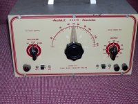
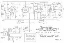
Picked this up on the bay. Seems to be very rare. Schematic is clear online but no manual. W/O a scheme available I would not have grabbed it. I liked that I recognize all the tubes unlike some other models.
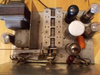
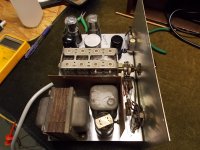
Looks to be 1949 from the pot and tubes. Scheme is 1948. Someone changed some caps, including the can and did some tack soldering that is horrendous. I plan to change most of the caps and resistors and upgrade the filters which were already “upgraded” last time.
The power supply wiring was apparently modified in one area and I doubt the person soldering had the know-how to intentionally modify it. Maybe there was a second schematic or update but I have not seen that.
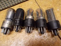
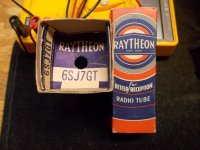
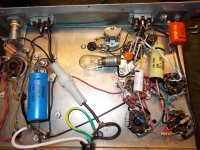
All the tubes check ok but the 6SJ7GT in there has a nearly spent getter. (Far left in the pic.) Scheme says metal for that spot and I picked up an NOS metal for $5 and a GT real cheap too. I may change the heaters to balanced with an artificial CT. I’m upgrading the wattage of the PS resistors. PT and choke check good. I did not power it up other than with all disconnected at the PT. Controls were dirty and some stuck but cleaned up nice. Adding a fuse. Not decided on a 3-prong cord yet. Maybe just polarized. I'm considering adding ventilation on top since the sides are barely ventilated.
Anyone see any red flags on the (pdf) scheme?
Looks to be 1949 from the pot and tubes. Scheme is 1948. Someone changed some caps, including the can and did some tack soldering that is horrendous. I plan to change most of the caps and resistors and upgrade the filters which were already “upgraded” last time.
The power supply wiring was apparently modified in one area and I doubt the person soldering had the know-how to intentionally modify it. Maybe there was a second schematic or update but I have not seen that.
All the tubes check ok but the 6SJ7GT in there has a nearly spent getter. (Far left in the pic.) Scheme says metal for that spot and I picked up an NOS metal for $5 and a GT real cheap too. I may change the heaters to balanced with an artificial CT. I’m upgrading the wattage of the PS resistors. PT and choke check good. I did not power it up other than with all disconnected at the PT. Controls were dirty and some stuck but cleaned up nice. Adding a fuse. Not decided on a 3-prong cord yet. Maybe just polarized. I'm considering adding ventilation on top since the sides are barely ventilated.
Anyone see any red flags on the (pdf) scheme?
Attachments
Last edited:
Missing the internal stabilizer lamp?
Sure is lovely clean in there!!
It is not a guitar amp. The ungrounded heater may be perfectly OK since it all runs at HIGH level.
I would not punch holes. In these things the BIG open-plate cap absorbs hum from thin air. Out in the open it will hum bad until you close the case. I would not worry about internal heat until you discover that you use it all day every day for years; then only cautiously. Since you can buy audio sources better and cheaper than this, I'd assume it is for display and occasional casual use. It was excellent for 1948 and is still fine in that form.
I would not fret over-much about a brown getter after 70 years. How long do you expect to live?
Power supply resistors? The 10k and 5.6K droppers? The 10K can't possibly dissipate near as much as the 100Ks downstream from it. The 5.6K likewise won't have the heat of the "47K to 51K 1W" parts.
A three wire cord doesn't hurt my feelings, but in general, Heath stuff was well designed and sturdy, and frankly doesn;t need reengineering. It works well stock, so update any tired old parts.
As PRR points out, there are two lamps in this unit. One is the pilot light on the panel, the other is the lamp in the oscillator circuit.
As PRR points out, there are two lamps in this unit. One is the pilot light on the panel, the other is the lamp in the oscillator circuit.
Thanx for all the comments. The tip on hum w/o the cover is very appreciated. The 3watt lamp is removed and good. I'll check the temp before drilling the top. The metal and glass 6J7 tubes arrived and the getter on one of the NOS GTs is similarly spent. (I bought 2 GTs.) I know they are NOS since they came in crazy Raytheon boxes that force you to rip the box to get the tube out. They say something about rejecting them if the seal is broken. The pins stick out the bottom almost as if you could still test them with an extended socket.
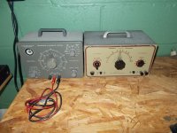
Yes, it is mostly for nostalgia and will look nice next to my Heathkit C-3 cap tester which works great and looks cool. Dad built a Heathkit TV around 1978 which still amazes me. We tuned it between channel 6 & 7 to get free HBO for a few years until the scrambling phase began.
Yes, it is mostly for nostalgia and will look nice next to my Heathkit C-3 cap tester which works great and looks cool. Dad built a Heathkit TV around 1978 which still amazes me. We tuned it between channel 6 & 7 to get free HBO for a few years until the scrambling phase began.
Attachments
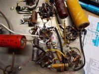
I decided to do a full overhaul. All caps and all resistors other than those on the range-selector. The NOS metal 6SJ7 tested the strongest and I figured its “shield” would be a good idea. I was seeing some crazy dual trace on the output after the rebuild. The pair would dance around each other and I could control their rotation direction and speed with the small adjustable cap. I starting thinking I should reduce the output 8u (using 10u) as a test. First, I hooked my DMM to the output and saw over 70 volts of dc. It drifted down as that output cap charged thru the meter. (I had the scope in ac coupling so the cap wasn’t charging thru it.) The charging time was long and would not complete. I added a 680k resistor across the output but it would not charge all the way.
I noticed the dancing duo was not on the cathode and that the signal strength at the cathode was over 5volts p-p. I decided to move the output to a cap off the cathode to resolve both issues. I included the 680k load/charging resistor which lets the 0.68u output cap charge up quick and stable. I tested with a 10k load and the output looks great. I verified the strength is consistant down to low frequencies thru the 0.68u. I don’t understand how having an 8u on the output like the scheme can work properly w/o placing huge dc on whatever you are injecting for quite some time.
I increased some cathode resistors to bring the current back down, to counter from today’s higher voltages.
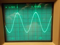
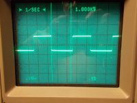
The square wave looks almost perfect other than the top traces being shorter than the bottom traces. I tried the adjustable cap but it does not affect that. (I’m fishing on its true function.) I guess that particular asymmetry in the square mode is not a big deal or even meaningful?
The heaters were running 6.9 volts which is over my comfort zone for tubes from 1949. 3 parallel 1Rs, inserted in line, brought it down to 6.3.
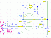
I don’t have an isolation setup on the bench and added a grounded power cord. The PT gets pretty hot after a while. I’m still undecided on adding a vent. I marked up the scheme with the (sine mode) voltages and changes and included here.
I noticed the dancing duo was not on the cathode and that the signal strength at the cathode was over 5volts p-p. I decided to move the output to a cap off the cathode to resolve both issues. I included the 680k load/charging resistor which lets the 0.68u output cap charge up quick and stable. I tested with a 10k load and the output looks great. I verified the strength is consistant down to low frequencies thru the 0.68u. I don’t understand how having an 8u on the output like the scheme can work properly w/o placing huge dc on whatever you are injecting for quite some time.
I increased some cathode resistors to bring the current back down, to counter from today’s higher voltages.
The square wave looks almost perfect other than the top traces being shorter than the bottom traces. I tried the adjustable cap but it does not affect that. (I’m fishing on its true function.) I guess that particular asymmetry in the square mode is not a big deal or even meaningful?
The heaters were running 6.9 volts which is over my comfort zone for tubes from 1949. 3 parallel 1Rs, inserted in line, brought it down to 6.3.
I don’t have an isolation setup on the bench and added a grounded power cord. The PT gets pretty hot after a while. I’m still undecided on adding a vent. I marked up the scheme with the (sine mode) voltages and changes and included here.
Attachments
Last edited:
It is highly unlikely that the square-er pin 6 is at 10.9V. The "zero" V drop in the 10K at pin 5 is also dubious.
What trimmer? It is probably for trimming Sine Flatness. (Note that it straddles the main sine tune cap.) If Sine output is flat from 200CPS to 1KC, then rises or falls to 2KC, diddle the trim to get 2KC equal to 200CPS. Re-check with 2KC-20KC and 20CPS-200CPS.
I am struggling to grok what sets Square symmetry. On other circuits there would be a centering trim. I am not sure if this one is supposed to self-trim via R-C action, or those two huge resistors at pin 6, or if it just was not important in the day. Within the likely uses of a G2 in 2018, I would not fret.
The square wave looks almost perfect other than the top traces being shorter than the bottom traces. I tried the adjustable cap but it does not affect that. (I’m fishing on its true function.)....
What trimmer? It is probably for trimming Sine Flatness. (Note that it straddles the main sine tune cap.) If Sine output is flat from 200CPS to 1KC, then rises or falls to 2KC, diddle the trim to get 2KC equal to 200CPS. Re-check with 2KC-20KC and 20CPS-200CPS.
I am struggling to grok what sets Square symmetry. On other circuits there would be a centering trim. I am not sure if this one is supposed to self-trim via R-C action, or those two huge resistors at pin 6, or if it just was not important in the day. Within the likely uses of a G2 in 2018, I would not fret.
Good catch on the 10.9V. I rewrote it wrong as it is 109V. With 98V on pin 4 of the 6SL7 and 109V on pin 6, I'm thinking it is biased off when in sine mode, explaining the lack of any drop on pin 5. I moved the switch positions in the scheme to show the figures are while in sine mode. In square mode, there is 11volts of drop on pin 5.
Thanx for the tip on the finction of the trimmer. I did notice that higher positions on the frequency knob where causing lower output.
Thanx for the tip on the finction of the trimmer. I did notice that higher positions on the frequency knob where causing lower output.
Those numbers seem correct. In simulation with a different tube I get 68V where you see 109V; 12AT7 may conduct better than 6SL7. No advantage one or the other, just different numbers.
At idle the bottom triode is slammed ON and as you say the top triode is hard-off. It is a 2-stage high-gain amplifier, the two triodes conducting alternately, moving charge in/out of the 10uFd cap on the two 50K resistors. The gain is high but not infinite; I see (in close-up) considerable rounding at the corners.
The asymmetry... in sim I have to let it run a bit, the bias settles somewhat. (In real life it would settle before you got your hand off the Sin/Sq switch.) It does seem to tend toward 50:50 conduction but only as a trend. Not inclined to fret about it because if you need SQUARE there are now better techniques; if you need a quick wideband response estimate of an audio amp this square does the job (does amp output look like source?).
Attachments
The trimmer worked to balance the signal strength across the control range. I ran it for a while and the top and the upper side vent air did not get too hot. Fun project. The ~1960 C-3 needed very little work as it had been overhauled properly and not too long ago. Each will get a corner of the bench now.
Thanx for all the feedback and help!
Thanx for all the feedback and help!
Attachments
- Status
- This old topic is closed. If you want to reopen this topic, contact a moderator using the "Report Post" button.
- Home
- Design & Build
- Equipment & Tools
- Heathkit G-2 Audio Generator