Yes of course, I would make sure the inputs are switched to 1Meg Zin and use a coupling cap. You need to do that for Ch 2 anyway.
I have never used that shaped level feature but agree it may be a good way to preserve dynamic range in as wide a band as possible, especially at the low side where the xformer starts to drop and PSRR is probably very high.
Jan
I have never used that shaped level feature but agree it may be a good way to preserve dynamic range in as wide a band as possible, especially at the low side where the xformer starts to drop and PSRR is probably very high.
Jan
Hello,
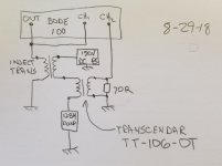
This is the page that I am on. The injection transformer is in the test loop. The object is to keep the high voltage isolated from the test equipment inputs and outputs.
Jan I see that you are intending to us capacitors for isolation. I am looking to the injection transformer for voltage isolation.
Ideally the injection transformer can do a better in terms of phase performance prior to Thru calibration. There is a much larger Home roll transformer on the bench that has much better low frequency performance that I will try next. The SET output transformer, also in the test loop will continue to be the limiting High frequency factor.
Thanks DT
We are moving to a new to us home on the cool California north coast. We will be gone for the long weekend. There will be MORE space for work and test benches. Jan you inspired me, looking at you SilentSwitcher video, I liked you work and listening spaces.
Attachments
Hello,
This is mostly proof of concept. Hook it all up with the tube and power supply, probe everything with a volt meter, confirm that there is current flowing through the SET, confirm that there are no wild voltages at the input of the injection transformer and output of the SET transformer. Connect the Bode 100. Output divides and goes to the injection transformer and Ch1 (reference) the output of the SET Transformer, across the 70 Ohm resistor, connects to Ch2 (input). (72 Ohms is the impedance of the Audeze LCD 2 headphones.)
Yes the DUT is the 12B4A SET. The injection transformer is also in the test loop. No smoke.
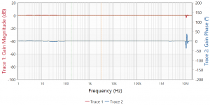
See the plots in Post 73.
The first plot is the test loop including the injection transformer. The second plot is the Output transformer only. In the first plot you can see the amplitude and phase effects pf the injection transformer.
See the plot in post 60.
This is the plot of the injection transformer only.
The next effort will be with Thru calibration and or a different injection transformer.
Thanks DT
This is mostly proof of concept. Hook it all up with the tube and power supply, probe everything with a volt meter, confirm that there is current flowing through the SET, confirm that there are no wild voltages at the input of the injection transformer and output of the SET transformer. Connect the Bode 100. Output divides and goes to the injection transformer and Ch1 (reference) the output of the SET Transformer, across the 70 Ohm resistor, connects to Ch2 (input). (72 Ohms is the impedance of the Audeze LCD 2 headphones.)
Yes the DUT is the 12B4A SET. The injection transformer is also in the test loop. No smoke.
See the plots in Post 73.
The first plot is the test loop including the injection transformer. The second plot is the Output transformer only. In the first plot you can see the amplitude and phase effects pf the injection transformer.
See the plot in post 60.
This is the plot of the injection transformer only.
The next effort will be with Thru calibration and or a different injection transformer.
Thanks DT
peaks and nulls stuff
Hello,
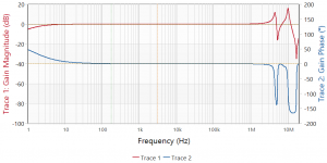
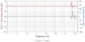
This is the injection transformer with Thru calibration. Same transformer as shown in posts #59 and #60. This Thru calibration thing is pretty clever.
However there looks to be limits. Above 10MHz the injection transformer does all that self resonance peaks and nulls stuff. Where the transformer gets all wobbly the Thru calibration does not have a chance.
Jackinnj,
Do you have plots using DC blocking capacitors with and without Thru calibration?
Thanks DT
Hello,
This is the injection transformer with Thru calibration. Same transformer as shown in posts #59 and #60. This Thru calibration thing is pretty clever.
However there looks to be limits. Above 10MHz the injection transformer does all that self resonance peaks and nulls stuff. Where the transformer gets all wobbly the Thru calibration does not have a chance.
Jackinnj,
Do you have plots using DC blocking capacitors with and without Thru calibration?
Thanks DT
Attachments
Jackinnj,
Do you have plots using DC blocking capacitors with and without Thru calibration?
Thanks DT
Not right at hand.
Here's the THS3121 Dual "rail driver"
Attachments
Hello,
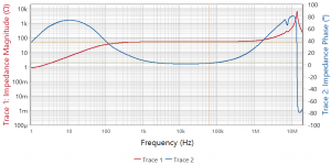
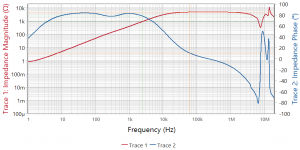
These plots are done with the much larger Home roll injection transformer. Both plots are done with the secondary terminated with a 5.62K resistor. The thinking is that the injection transformer secondary will be in series with the DUT that has 5000ish ohms across it. The value of the Thru calibration resistor can be adjusted to match the impedance of the DUT.
The first plot is without Thru correction.
The second plot is with Bode-100 Thru correction.
I like the looks of this injection transformer for PSRR testing of circuits up to the voltage rating of the transformer wire insulation.
Thanks DT
The wobbly part is above 4MHz.
Attachments
Can you run the impedance plot on the primary -- load the trafo with 50R and 5K. Maybe we can design a zobel.
You can calibrate the bode 100 in impedance mode with 1206 SMD resistor and Pomona BNC to Banana adapter -- open, short, load. Make sure that the value of the resistor matches that in the advanced setting pop-up dialogue.
You can calibrate the bode 100 in impedance mode with 1206 SMD resistor and Pomona BNC to Banana adapter -- open, short, load. Make sure that the value of the resistor matches that in the advanced setting pop-up dialogue.
Here's the Omicron application note for trafo modeling:
https://www.omicron-lab.com/fileadm...ling/App_Note_Transformer_modelling_V_2_0.pdf
https://www.omicron-lab.com/fileadm...ling/App_Note_Transformer_modelling_V_2_0.pdf
Hello,
Over the summer I spent some quality time with the book Power Integrity by Steven Sandler including Chapter 7 about Measuring Impedance. I also spent time with the transformer modeling Application Note. I am trying to understand what I know.
If you make all the measurements and calculations discussed in the Application Note you have everything you need for a transformer SPICE model.
Jack,
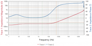
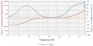
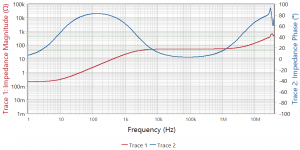
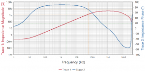
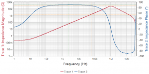
The big Home Roll injection transformer impedance plots looked a little messy. So I tested the little brother transformer with the terminations that you recommended. Plus I included 3 more termination:
Primary shorted or 0 Ohms.
Primary 10 Ohms.
Primary 50 Ohms.
Primary 4.99K Ohms.
Primary open.
See the attached plots. I do not see any sharp peaks where a zobel would help.
Looking at the plots it becomes clear to me that termination impedance (Load) has everything to do with the transfer curves of the injection transformer. If there is no injection resistor per say and the injection transformer coil is in series with the power supply it looks to me that the effective termination impedance of the injection transformer is closer to the 5K or higher impedance end of the range of things.
See Post 59 to see the transformer.
Thanks DT
Over the summer I spent some quality time with the book Power Integrity by Steven Sandler including Chapter 7 about Measuring Impedance. I also spent time with the transformer modeling Application Note. I am trying to understand what I know.
If you make all the measurements and calculations discussed in the Application Note you have everything you need for a transformer SPICE model.
Jack,
The big Home Roll injection transformer impedance plots looked a little messy. So I tested the little brother transformer with the terminations that you recommended. Plus I included 3 more termination:
Primary shorted or 0 Ohms.
Primary 10 Ohms.
Primary 50 Ohms.
Primary 4.99K Ohms.
Primary open.
See the attached plots. I do not see any sharp peaks where a zobel would help.
Looking at the plots it becomes clear to me that termination impedance (Load) has everything to do with the transfer curves of the injection transformer. If there is no injection resistor per say and the injection transformer coil is in series with the power supply it looks to me that the effective termination impedance of the injection transformer is closer to the 5K or higher impedance end of the range of things.
See Post 59 to see the transformer.
Thanks DT
Attachments
Last edited:
- Status
- This old topic is closed. If you want to reopen this topic, contact a moderator using the "Report Post" button.
- Home
- Design & Build
- Equipment & Tools
- The Bode-100 thread