I'm looking for a simple yet practical solution to test the performance of low power amps at various power points. What I've got on hand is decent soundcard (esi juli@) with balanced in-out and a 20mhz analog scope. So what I'm missing is a practical interface in between the soundcard, the scope, the load and the amp. I'm getting fed up of the mess of wires I currently play with.
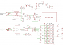
Attached is the preliminary schematic of such an interface.
At the heart of it are 36 33R/2W resistors. In parallel/serie (12*3), they are equivalent to a 8.25 load.
To connect to the soundcard output, there is a ina134 receiver. It is followed by a pot and a buffer. This feed the amp's input, with the ability of controlling the amp power in case of a power amp without volume control.
To connect on the other hand to the soundcard input, there is a drv134 driver. It is fed from a voltage divider in // with the load. The values of the divider are chosen so that they correspond at various power points for a full signal at the input of a given soundcard (+20dbu for the juli@). As the voltage needed for 1W@8R is quite low, a small gain stage is inserted in between the divider and the drv134.
To be of use with the scope, there are two more options. One is a sine to square wave converter to test stability (based on a schematic by Mooly iirc) and the other is the possibility to add caps in // with the resistors, for the same reason.
All this should fit on a 10*10cm pcb, with cutouts under the resistors to allow further cooling by a fan fitted under the pcb.
The power could come from USB. With some dc-dc converters, the board could be kinda isolated from the computer, being only connected through balanced lines.
There are still some things missing such as overload protection, the ability to disable the square wave converter (a noisy load) for sensitive testing.
What do you think ?
Attachments
Last edited:
Going slowly forward.
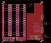
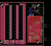
Here's a first idea of what the pcb would look like. It's still missing the power section and the sine to square wave converter. It's a bit simplified, a quad jfet opamp replacing the drv134-ina134.
The layout is made in such a way that most of the low level circuitry is hidden under the board and almost everything on top is at 0v, to avoid shorts if the board is simply screwed in on a wood piece.
Attachments
Most important is GND loops between soundcard Line In and Line Out.
That's probably true. Everything will be earthed : the amp, the desktop pc, the oscilloscope and thus that board.
Some ground loop breaker resistors in between the gndplane section and pin1 of the input/output going to the soundcard might do some good. And maybe connect the shield to a dedicated low impedance track going to the speaker return directly.
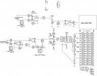
I'm probably going to drop the sine to square converter. It would be better served by a dedicated small board.
Attachments
ESI Juli is a very useful card for measuring since it offers single-ended and balanced inputs/outputs working simultaneously. The balanced input offers 40Vpp range without any voltage dividers.
Ground loops are always a problem in measurements. I am avoiding them by using class II measurement PC with display over network Headless Amplifier Measurement Workstation source code +3D models for Juli at GitHub - pavhofman/measurement-station: Audio measurement workstation
The speaker measurement load I have tested offers both balanced and single-ended mode, two ranges, option to connect/disconnect output ground to avoid the loop, the same for output to scope - hifi.slovanet.sk ::, I am currently working on a nicer enclosure for the rig, picture of the initial non-enclosed version https://raw.githubusercontent.com/pavhofman/measurement-station/master/images/14.jpg
As the first step I designed a 3-pushbuttons extension to regular 20A rocker switches for switching the combination of 4ohm and 8ohm power resistors (i.e. 2.7, 4, 8ohm load) - pictures (the discussion is in czech) hifi.slovanet.sk :: Zobrazi tmu - Jednoelov mic PC s PCI zvukovkou v izolan td II . I will put the Fusion360 model of the switch to my github repository .
I actually didn't know you could use both sets of inputs/outputs of the juli@ at the same time. That's good to know. Thanks for posting your project too, that's a good source of inspiration. To be true, I'm also planning to use the focusrite 18i8 at times, hence the +20dbu/+16dbu switch.
As far as groundloops are concerned, I think it shouldn't be too bad as it is. The signal ground "island" only connect to the gnd load at one point. The earth pins of the incoming/outgoing signal also return to the load. So there shouldn't be any ground current interfering with the differential sensing. If I'm wrong, I'd be gladly corrected.
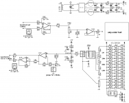
I'm posting pretty much final schem and board. I've yet to clean up the names on the pcb so I'll post the eagle files later. The physical construction should be a fan at the bottom, a first pcb filled only with power resistors fixed above it, a second pcb fully filled on top (there are cutouts under the resistors for airflow). It would allow a conservative testing of 50W/8R-100W/4R, double that short term. The holes on the pcb are on a 83mm grid, to fit on a 92mm pc fan. There are holes to connect thick wires and a switch between two load pcb.
Power supply wise, all should be powered from a usb port or a small 5v adapter. An artic f9 fan only needs 90mA when run at 5V and the opa4134 only needs about 20ma. So even with a dc-dc converter, we're not taxing the usb port.
In terms of use, it's fairly simple. One pot controls the input signal, to adjust the power fed to the load. If one uses the fixed resistor ladder, a full scale signal at the input of the soundcard (+16 or +20dbu) corresponds to a particular power point (indicated for 8r, to be doubled for 4r). You just have to slowly increase the pot (starting from zero) until you get close to clipping. If another power point is needed, another pot can be used as divider. But then you need at least a good multimeter and a 50hz/60hz signal (or better a scope) to adjust the power you want.
There are a few diodes/led to limit the output signal (at about 5Vpp before the output balanced line driver, full signal being 4Vpp). It will still clip the input of the soundcard but shouldn't burn it.
As far as groundloops are concerned, I think it shouldn't be too bad as it is. The signal ground "island" only connect to the gnd load at one point. The earth pins of the incoming/outgoing signal also return to the load. So there shouldn't be any ground current interfering with the differential sensing. If I'm wrong, I'd be gladly corrected.
I'm posting pretty much final schem and board. I've yet to clean up the names on the pcb so I'll post the eagle files later. The physical construction should be a fan at the bottom, a first pcb filled only with power resistors fixed above it, a second pcb fully filled on top (there are cutouts under the resistors for airflow). It would allow a conservative testing of 50W/8R-100W/4R, double that short term. The holes on the pcb are on a 83mm grid, to fit on a 92mm pc fan. There are holes to connect thick wires and a switch between two load pcb.
Power supply wise, all should be powered from a usb port or a small 5v adapter. An artic f9 fan only needs 90mA when run at 5V and the opa4134 only needs about 20ma. So even with a dc-dc converter, we're not taxing the usb port.
In terms of use, it's fairly simple. One pot controls the input signal, to adjust the power fed to the load. If one uses the fixed resistor ladder, a full scale signal at the input of the soundcard (+16 or +20dbu) corresponds to a particular power point (indicated for 8r, to be doubled for 4r). You just have to slowly increase the pot (starting from zero) until you get close to clipping. If another power point is needed, another pot can be used as divider. But then you need at least a good multimeter and a 50hz/60hz signal (or better a scope) to adjust the power you want.
There are a few diodes/led to limit the output signal (at about 5Vpp before the output balanced line driver, full signal being 4Vpp). It will still clip the input of the soundcard but shouldn't burn it.
Attachments
Ground loops are usually closed via ground cables of the power supplies.
The problem with a soundcard in a regular earthed (grounded, class I) PC is the voltage difference between 0V potential of the soundcard (cinch sleeve) and 0V = PE line at the ATX PSU. It is caused by huge currents (tens of amps) flowing through ground traces on the motherboard. Usually the PCI (PCI-e, USB) slot feeding the soundcard is located on the motherboard far away from the power socket. Every motherboard is differently designed, every load generates different noise pattern.
Balanced inputs (even to single ended outputs on the other side) help a lot (as I learned in Adding an Amp into Thin-Client PC ). And of course breaking the ground loop altogether by not using class I PC (incl. all attached devices, typically a monitor).
")
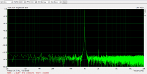
The pcb arrived today, I populated the low level section. I've yet to solder the power resistors. Before doing it, I quickly ran a test in ARTA, on a focusrite 18i8. So that's just the opamp section, with a connection direct from "amp input" to "amp output".
Seems ok enough (the graph attached is at -10dbfs). I can get the thd+n a bit lower if the soundcard input is at -5dbfs but then thd goes up a bit. I'm going to redo the test on the juli@ tomorrow.
Btw, the performance of the 18i8 is ok at 1khz and 48khz sample rate. Things aren't that good at higher frequencies and sample rates. I'm curious to compare it to the juli@.
Attachments
- Status
- This old topic is closed. If you want to reopen this topic, contact a moderator using the "Report Post" button.
- Home
- Design & Build
- Equipment & Tools
- 40W/8R not so dummy load for amplifier testing