I have some experience with ferrites and other magnetic materials, and my advice for low-distortion (not even ultra-low THD) is to use none: with regular MnZn ferrite, with an air-gap the same size as the core (a cylindrical coil in fact), the distortion is easily detectable.LC passive band-pass filters without any magnetic core material are easy to build for frequencies of say 1kHz and higher, but how about 20Hz or so?. Then one need some magnetic core material, otherwise the dimensions of the inductors get way too large. But then things like saturation and hysteresis come into play and will (most likely) increase distortion.
Any ideas?
Iron is even worse, due to its hysteresis
NiZn ferrites or iron powder/polymer might be better, I think I will do some tests, as I will also need ultra-low THD coils in the future (but I am not too optimistic).
VLF air-core coils aren't difficult: they take up some space and some copper, but they are perfectly manageable.
The real problem is their sensitivity to stray fields (large dimensions, lots of turns): it is a real nightmare in a modern test environment.
I think Scott Wurcer had a brush with the subject
Weighting
Dear Edmond:
I am trying out 1.59.2 Demo on Windows 7. Having tried most PC based audio SW, I am intrigued by your SW!
A few comments/questions:
1) In Prefrences one can choose HP and LP filters. Say 20 and 20kHz. But when I look at the RAW spectrum it goes down to 0.2Hz and above 20kHz. This is a little confusing. Should the range not be 20-20k?
2) Would it be possible to show what noise BW (A-weighted, or freq range) in the result presentation. That is, -105.3 dBA or -105.3 dB(A), -123.4 dB(20-20kHz)?
3) If I enter 20 000 as BW, what start and stop freq are used?
4) If I use A-weighted BW, should the raw spectrum not reflect that, ie be falling down towards lower freq?
Best regards,
No, it is what it is. The HP and LP filters act only on the signal itself* and not on some scale. However, the bandwidth of the THD spectrum can be set by the Number of harmonics and the kind of filtering by choosing Gaussian or Brick-wall.
As for the raw spectra, they are only meant as a kind of 'treat' and of secondary importance. The main purpose is to detect hum and other spurious signals.
For those interested in the harmonics, just have a look at the THD spectrum. Remember, DiAna is a distortion analyzer (not just another spectrum analyzer).
As for the Noise BW (A/B/C-weighted), these settings have only effect on the calculation of the Signal/Noise ratio and nothing else (as it should be).
Have fun with DiAna,
Cheers,
E.
* To be more precise, the HP filter act on the input signal and the LP filter only act on the residual. Also note that the THD spectrum is based on this residual.
VLF air-core coils aren't difficult: they take up some space and some copper, but they are perfectly manageable.
The real problem is their sensitivity to stray fields (large dimensions, lots of turns): it is a real nightmare in a modern test environment.
I think Scott Wurcer had a brush with the subject
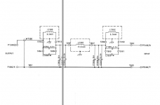
FWIW here is the circuit and construction details on the RE CLT-1 Radiometer CLT-1 low pass filter. Its a 10 KHz LP filter that helps get -170 dB at 30 KHz, at least -160 dB passing 1 Watt at 10 KHz. As I remember the internal source is .01% or -80 dB so the filter gets 80 or 90 dB at 2 octaves.
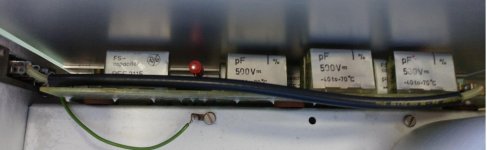
Success is all about construction details. The size of the coils and the size of the shields should help for a sense of scale. For 1 KHz or 100 Hz I don't think you need to scale directly (those would be huge) but I don't know.
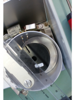
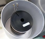
There is a matching transformer in it to get to 1 KV or 100 mV into a component. Its a big pot core, almost the size of a bowling ball. Even though the instrument is in a triple case with each module in an aluminium box and the whole system is a double box its still quite sensitive to external fields around 30 KHz which was a problem back in the days of CRT monitors, especially VGA monitors.
Attachments

Last edited:
 Building it this way, such a filter becomes a project on it's own right, let alone at lower frequencies. I really hope it can also be done with ferrite pot-cores without too much distortion.
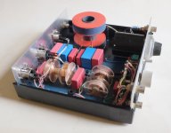
Below a picture of my (simple) band-pass filters for 1, 5 and 20kHz (critically coupled).
Cheers,
E.
PS Note that the resonators are inductively coupled, resulting in a galvanic isolation between input and output too (avoiding ground loops).
Attachments
Last edited:
Use really good caps. in practice that would be Air, Teflon, Polystyrene and construction would be important. Many years ago I had some custom teflon caps made with a plastic housing and copper wire by Component Research. That company doesn't exist anymore. however a different company that absorbed them has a pretty complete into into these caps: http://www.us-tech.com/customized/c...rs/pdfs/wound film capacitors white paper.pdf
Supposedly NPO ceramic caps are as stable and low distortion as teflon or polystyrene but there is some debate.
Supposedly NPO ceramic caps are as stable and low distortion as teflon or polystyrene but there is some debate.
This is about dielectric distortion. How about mechanotransduction distortion? Every capacitor is quite imperfect combo of electrostatic speaker and condenser microphone. Capacitors "sing", sometimes loudly, when audio signal is applied. Becaause highest quality capacitors (e.g.. air and vacuum) are large, shielding may be the same problem as with large air core inductors.
My point is that capacitors, like inductors, have their own set of distortion problems that call for scrutiny in applications that require very low distortion.
Inductors may in fact be less problematic than capacitors. Modern ferromagnetics may have very low hysteresis and almost zero magnetostriction combined with mu of 50,000 or more and working frequencies up to 100 kHz, which allows making a low distortion inductor of over 1000 H and size of less than cubic inch.
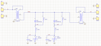
I have made notch filters for 10 MHz+-1.5 KHz to remove some phase noise at least
locally so I can get an idea where it pays to optimize.
This had to be implemented with crystals, an LC resonance would be much too wide.
But a crystal behaves like a series LC and in the KHz range LC will do.
A crystal has a loss resistance like 20 to 50 Ohms at resonance, so we need at least
a 400..500 Ohms environment to get an effect. This is done here with the transformers.
It could be done with resistors.
The crystals simply shunt the part of the spectrum at their series resonance to GND.
Since the phase noise happens equally above and below the oscillator's frequency,
we need 2 notches, one at +1.5 KHz and one at -1.5 KHz, otherwise we get 3 dB
at best.
The beauty is, that the series circuits are exited only by the little bit of noise that
happens to be at their frequency. They completely ignore the carrier. I can send
real power through that filter with no damage. If I would tune the oscillator across
the series resonance, that would shatter the crystal.
So, the distortion of the resonators at AF would only be triggered by the already
small power level of the harmonic, not by the fundamental.
Attachments
Many many years ago when i really didn't know much I built an audio frequency crystal oscillator with a 7860 Hz crystal. I didn't know any better and the vendor supplied one!! It was 4" long in the case. I used it with some RTL circuitry (which shows how long ago). It may still be possible to get crystals like that. Here is more on these strange beasts: Low Frequency crystal oscillator
Last edited:
Something similar on eBay: BLILEY CRYSTAL QUARTZ # 924A211 NSN: 5955-00-070-7008 9.58 KHZ ( B931) | eBay It would be real brute force to use something like this in an audio frequency filter but seems possible.
Edmond-
I'm working on setting up the notch filter stuff however I'm rather confused by the process and what data I should see. I'm using the latest version and trying the following-
Channel a test channel b ref (pre notch filter). I click on find notch frequency it seems to do something but no obvious indication except the phase of the upper wave changes. If i click characterize notch filter it seems to get no data when i go to save. Turning on and off the notch compensation does something but with all the gears inside I'm not sure what I'm looking at. Also will this work with an external source using the ref channel to monitor the source? The results I'm getting do not make sense.
Notch stuff
Hi Demian,
It's too early to use the (new) notch functions, because this part of DiAna is not finished yet. I also have to update the documentation. Without that, it's hard to figure out how to handle this notch stuff exactly. My apologies for the inconvenience. I hope next week it will be ready.
Cheers,
E.
Last edited:
Notch filter
Dealing with notch filters
For ultra low level distortion measurements over a longer period of time, it's important to keep the test frequency exactly at the notch filter dip. Since there will always be some drift, that means that either one have to tune the notch filter on the fly, or -more easily- to tune the signal generator while running. But, in case of the latter, the FFT will get smeared out, resulting in false THD readings.
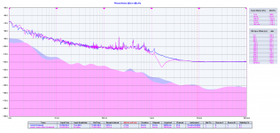
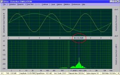
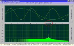
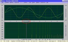
Now let's see how DiAna copes with this issue. As a proof of concept I've subjected the three kinds of FFT's (actualy FHT's) to a simulated test signal, swept between 987 and 1007Hz, together with a 3rd harmonic at -120dB.
As expected, the ordinary FFT's (both coherent and incoherent) are smeared out over several frequency bins. Also the harmonic levels are too low: -142.45dB respectively -129.52dB (see fig. 1 and fig.2)
The so called THD (and DiAna's primary) spectrum however, doesn't suffer under swept frequency conditions. The 3rd harmonic is still exactly -120.00 dB, see fig 3. In other words, this is the right way to go forward.
Cheers,
E.
Dealing with notch filters
For ultra low level distortion measurements over a longer period of time, it's important to keep the test frequency exactly at the notch filter dip. Since there will always be some drift, that means that either one have to tune the notch filter on the fly, or -more easily- to tune the signal generator while running. But, in case of the latter, the FFT will get smeared out, resulting in false THD readings.
Now let's see how DiAna copes with this issue. As a proof of concept I've subjected the three kinds of FFT's (actualy FHT's) to a simulated test signal, swept between 987 and 1007Hz, together with a 3rd harmonic at -120dB.
As expected, the ordinary FFT's (both coherent and incoherent) are smeared out over several frequency bins. Also the harmonic levels are too low: -142.45dB respectively -129.52dB (see fig. 1 and fig.2)
The so called THD (and DiAna's primary) spectrum however, doesn't suffer under swept frequency conditions. The 3rd harmonic is still exactly -120.00 dB, see fig 3. In other words, this is the right way to go forward.
Cheers,
E.
Attachments
Hi Demian,Edmond-
I'm working on setting up the notch filter stuff however I'm rather confused by the process and what data I should see. I'm using the latest version and trying the following-
Channel a test channel b ref (pre notch filter). I click on find notch frequency it seems to do something but no obvious indication except the phase of the upper wave changes. If i click characterize notch filter it seems to get no data when i go to save. Turning on and off the notch compensation does something but with all the gears inside I'm not sure what I'm looking at. Also will this work with an external source using the ref channel to monitor the source? The results I'm getting do not make sense.
In the meantime I discovered that the option "Characterize notch filter" is broken since the last couple of updates. I didn't check this function after each modification, because its a bit obsolete by now and will be replaced by a more convenient function. Nevertheless my apologies for this and I will figure out why it went wrong. It is best to ignore version 1.59.2 and wait for an upgrade.
PS or is it a sample wiring issue?
Cheers,
E.
Last edited:
Dealing with notch filters
For ultra low level distortion measurements over a longer period of time, it's important to keep the test frequency exactly at the notch filter dip. Since there will always be some drift, that means that either one have to tune the notch filter on the fly, or -more easily- to tune the signal generator while running. But, in case of the latter, the FFT will get smeared out, resulting in false THD readings.
Now let's see how DiAna copes with this issue. As a proof of concept I've subjected the three kinds of FFT's (actualy FHT's) to a simulated test signal, swept between 987 and 1007Hz, together with a 3rd harmonic at -120dB.
As expected, the ordinary FFT's (both coherent and incoherent) are smeared out over several frequency bins. Also the harmonic levels are too low: -142.45dB respectively -129.52dB (see fig. 1 and fig.2)
The so called THD (and DiAna's primary) spectrum however, doesn't suffer under swept frequency conditions. The 3rd harmonic is still exactly -120.00 dB, see fig 3. In other words, this is the right way to go forward.
Cheers,
E.
Impressive. Edmond, a question. What would be the impact if the signal is fixed in freq and the notch drift? How important is it that the notch depth is constant?
I think the basic question is, why do you want to use a (software, I understand) notch? Where is that used for in DiAna?
Jan
Hi Jan,Impressive. Edmond, a question. What would be the impact if the signal is fixed in freq and the notch drift? How important is it that the notch depth is constant?
I think the basic question is, why do you want to use a (software, I understand) notch? Where is that used for in DiAna?
Jan
These are good question. As for the notch frequency, I thought it was important to compensate for a possible drift, because there was much talk about tunable oscillator and filters on the "other" thread. How important, I don't know yet, I've to figure that out (which can take hours and hours waiting for a substantial drift and to average out the noise).
As for the notch dept, well, that is of secondary importance, but nice to know anyhow in order the restore the fundamental for example.
As for your last question, firstly, I'm also using a hardware notch (at the moment single ended, but later on a balanced one; thank you for schematic) and why using such a filter? Just to lower the THD measurement floor. This seems to be a holy grail, right?
Cheers,
E.
PS The bug reported in the previous post was indeed a wiring problem, that can be remedied by a minor software change.
( "sample wiring issue?" read as "simple wiring issue?")
Last edited:
- Home
- Design & Build
- Equipment & Tools
- DiAna, a software Distortion Analyzer