Ok guys (and gals!), I know that as soon as the word "universal" is uttered, someone manages to find an exception, but let's try anyway....
I already had a number of "testers" (more test jigs, in fact) for that task, and even without that, it is possible to test a crystal using a network analyzer or a similar method, but to do that in a reasonable amount of time, you need to know the target frequency firsthand.
None of my jigs was even half-universal: they relied on average parameters values and most had some additional reactive components.
If you search the net, this is typically what you are going to find:
www.arrl.org/files/file/QEX_Next_Issue/Sept-Oct2016/Brown2.pdf
Crystal Testing Circuits
Mostly Colpitts oscillators, sometimes with switchable components, or some more elaborate circuit, but never truly universal (and automatic)
My most universal tester was an ECO (Emitter Coupled Oscillator), requiring no other reactance than the crystal itself, but it wasn't really universal, because of the extremely wide range of parameters possible: common crystals come in fundamental frequencies ranging from several kHz to several tens of MHz, a 1 to 104 range, series resistances range from a few ohms to several tens of kiloohms, sometimes more than 100kΩ, more than 1 to 104, and motional parameters vary even more wildly.
Making an oscillator capable of finding the exact resonance frequency, without errors (like parasitic modes) or shattering the crystal (yes, it can happen) is no mean task.
My first choice was a sophisticated version of the ECO, and it worked great, at least with all "modern" crystals: the ones in metal, glass, ceramic or epoxy cases.
Older ones have a big bakelite case, and have a "dead" parallel capacitance of several tens of pF's.
The problem is that the ECO degenerates into a relaxation oscillator when presented with a sufficient capacitance, and that's what happened with these crystals.
Compensating for parallel capacitance is possible, but then it impairs the VHF capabilities.
In the end, I (reluctantly) opted for a Pierce type oscillator, with carefully chosen components and additional tricks, like cascoding, variable transconductance and gyrator load:
To be continued...
Attachments
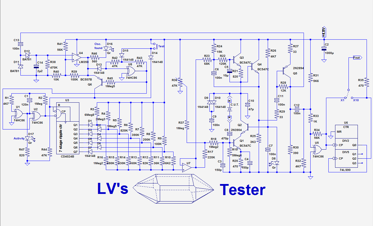
The left side of the schematic (CD4024, etc.) probably looks strange and unexpected for such a circuit.
In fact, given the possible range of frequency and parameters, including parasitics like input sockets and possible test leads, a fixed-conditions oscillator is not possible: the level of impedances, transconductance needs to be made variable.
The logical way to do that would be to include a servo, to control the main bias current and the resulting parameters, impedance and transconductance.
That's normally what is done in good quality oscillators of various types.
Unfortunately, this well-proven approach is not usable here: when no crystal (or a faulty one) is inserted, the servo will be stuck to its maximum, because it tries to cause an oscillation when none is possible.
As soon as you insert a crystal, the first and most obvious resonance will be found, and if it is a low-frequency crystal, having a frequency of a few kHz or tens of kHz and a series resistance of tens of kiloohms, this will be the quartz capacitance + series connection wiring, in the VHF range.
The servo will lock onto that spurious resonance, and stay there because there is no reason to go elsewhere.
Ideally, when nothing is inserted, the servo should be clamped to its low limit, and only released when something is inserted, but the method is not 100% safe, as the servo might need to overshoot before it stabilizes, with the risk of skipping the first, lowest resonance, which is in principle the intended target.
Thus, instead of a servo, I opted for a start/stop system: when the DUT is ready to be tested, the test is initiated (beginning with the low end of bias), and stops as soon as an oscillation is detected.
This method is much more reliable.
The CD4024 in conjunction with a special D/A converter generates the scanning ramp and holds it when an oscillation is found.
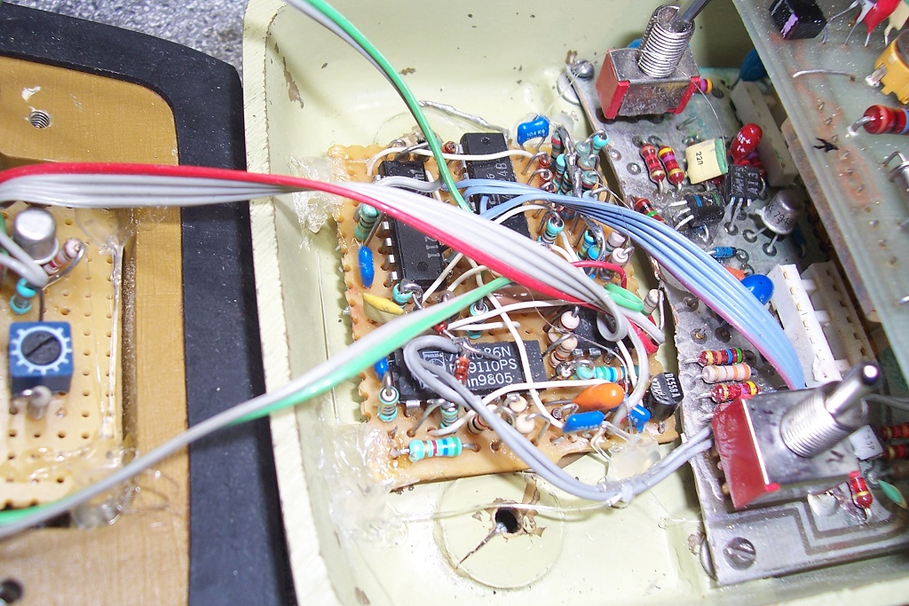
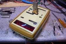
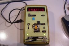
I will explain the curious details later, in the mean time, here are some pics of my build: I have grafted my tester into an old, worthless frequency-meter, for convenience:
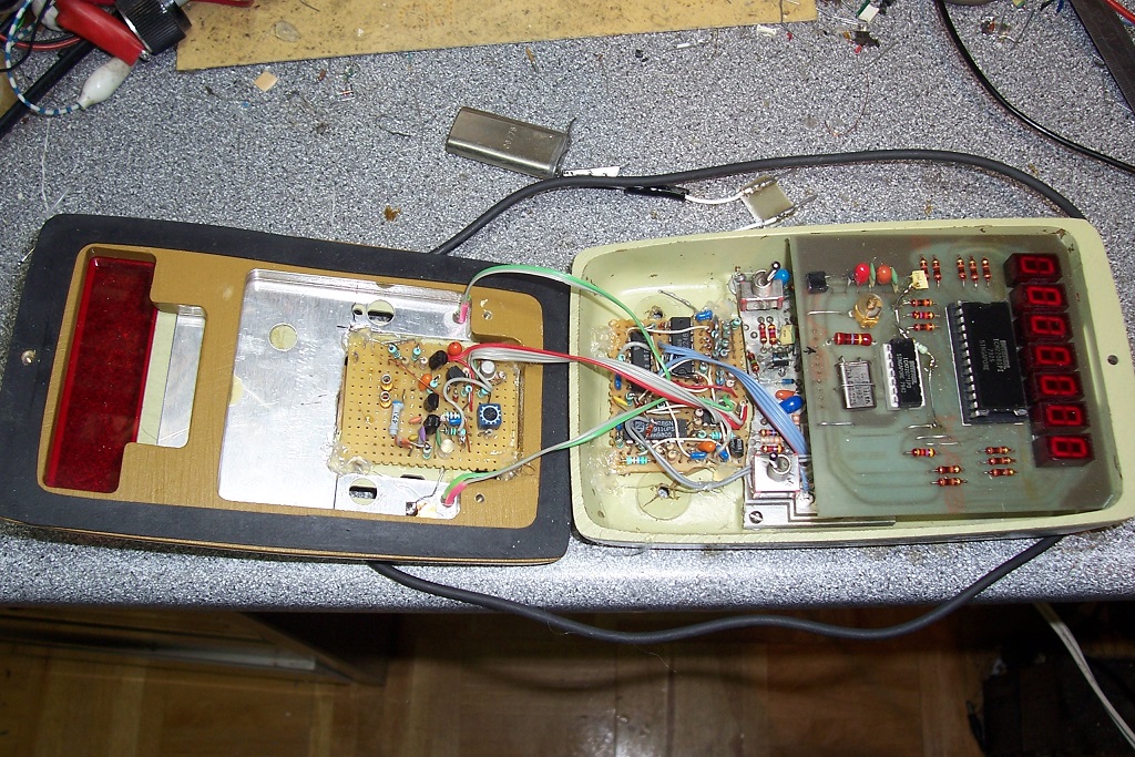
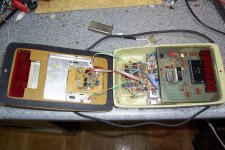
On the left is the oscillator part, on the right the control circuit. I have kept a part of the original frequency-meter board, to support the existing switches, and hacked off the rest.
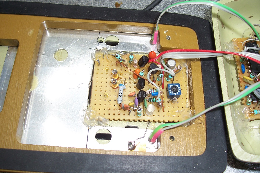
The oscillator board:
The control board:
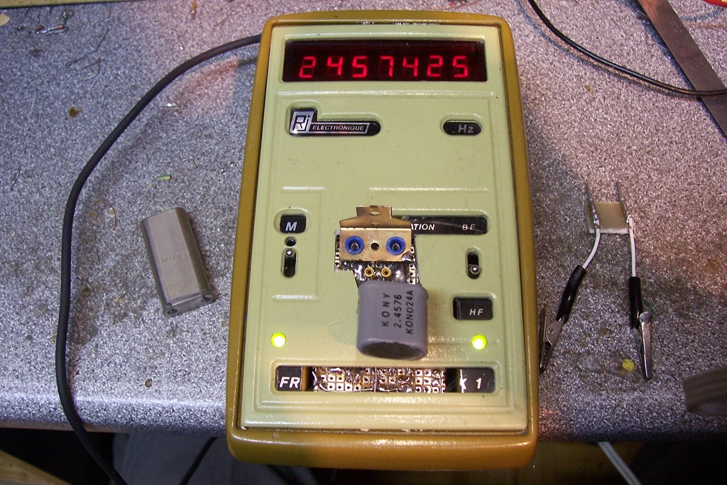
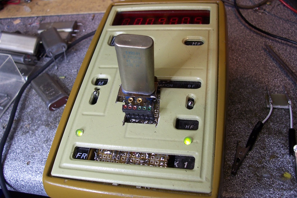
The instrument in action:
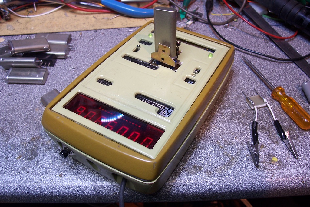
Rear view, with the start button:
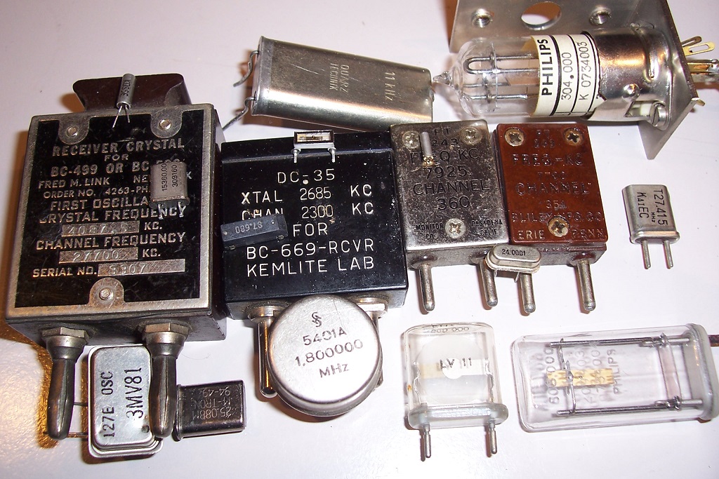
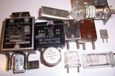
A small selection of testable samples, big and small:
In fact, given the possible range of frequency and parameters, including parasitics like input sockets and possible test leads, a fixed-conditions oscillator is not possible: the level of impedances, transconductance needs to be made variable.
The logical way to do that would be to include a servo, to control the main bias current and the resulting parameters, impedance and transconductance.
That's normally what is done in good quality oscillators of various types.
Unfortunately, this well-proven approach is not usable here: when no crystal (or a faulty one) is inserted, the servo will be stuck to its maximum, because it tries to cause an oscillation when none is possible.
As soon as you insert a crystal, the first and most obvious resonance will be found, and if it is a low-frequency crystal, having a frequency of a few kHz or tens of kHz and a series resistance of tens of kiloohms, this will be the quartz capacitance + series connection wiring, in the VHF range.
The servo will lock onto that spurious resonance, and stay there because there is no reason to go elsewhere.
Ideally, when nothing is inserted, the servo should be clamped to its low limit, and only released when something is inserted, but the method is not 100% safe, as the servo might need to overshoot before it stabilizes, with the risk of skipping the first, lowest resonance, which is in principle the intended target.
Thus, instead of a servo, I opted for a start/stop system: when the DUT is ready to be tested, the test is initiated (beginning with the low end of bias), and stops as soon as an oscillation is detected.
This method is much more reliable.
The CD4024 in conjunction with a special D/A converter generates the scanning ramp and holds it when an oscillation is found.
I will explain the curious details later, in the mean time, here are some pics of my build: I have grafted my tester into an old, worthless frequency-meter, for convenience:
On the left is the oscillator part, on the right the control circuit. I have kept a part of the original frequency-meter board, to support the existing switches, and hacked off the rest.
The oscillator board:
The control board:
The instrument in action:
Rear view, with the start button:
A small selection of testable samples, big and small:
Attachments


The core of the tester is built around Q1, the oscillator's active element.
The oscillator is of the Pierce variety, but to maximize the possible range of operation, the transistor has been cascoded, and its collector load is a gyrator, because no single choke can be good for a range of 5kHz to 50MHz.
The bias current is made variable, allowing the control of the key parameters of the oscillator, its transconductance, of course, but also the general impedance level.
This is very important, because low-frequency crystals have very high impedance levels, and operate under unfavorable conditions: the capacitors C3 and C10 are a tradeoff, but at the frequency extremes, they become seriously marginal.
The gyrator also benefits from variable bias, for the same reason.
The bias is generated by a particular, non-linear DAC: its transfer function is exponential.
This is necessary to keep a good resolution at low bias levels: a variation from 100mV to 200mV above the Vbe level is as is important as a variation from 1V to 2V.
It is in fact what AD names a "LOGDAC", but where AD uses brute force with a massive addition of bits, I use simpler, analog method.
The result is an exponential range, from 1 Vbe to Vdd, exactly what is required:
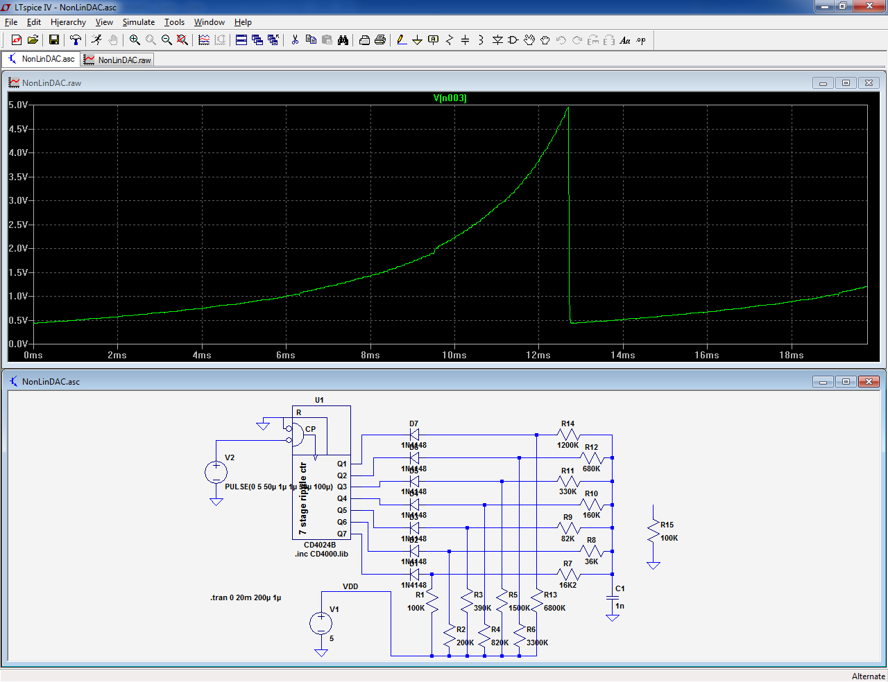
The transfer function isn't very clean, because most resistor's values are rounded to the E24 series, but it is perfectly sufficient for the task at hand.
The oscillator is of the Pierce variety, but to maximize the possible range of operation, the transistor has been cascoded, and its collector load is a gyrator, because no single choke can be good for a range of 5kHz to 50MHz.
The bias current is made variable, allowing the control of the key parameters of the oscillator, its transconductance, of course, but also the general impedance level.
This is very important, because low-frequency crystals have very high impedance levels, and operate under unfavorable conditions: the capacitors C3 and C10 are a tradeoff, but at the frequency extremes, they become seriously marginal.
The gyrator also benefits from variable bias, for the same reason.
The bias is generated by a particular, non-linear DAC: its transfer function is exponential.
This is necessary to keep a good resolution at low bias levels: a variation from 100mV to 200mV above the Vbe level is as is important as a variation from 1V to 2V.
It is in fact what AD names a "LOGDAC", but where AD uses brute force with a massive addition of bits, I use simpler, analog method.
The result is an exponential range, from 1 Vbe to Vdd, exactly what is required:
The transfer function isn't very clean, because most resistor's values are rounded to the E24 series, but it is perfectly sufficient for the task at hand.
Attachments
The combination of variable bias + cascode + gyrator in the oscillator probably looks a bit of overkill, and in fact, it is in a way: for example, if the cascode is omitted, it is still capable of making my most difficult VLF crystal oscillate, but with reduced margins:
For the complete circuit, oscillation is able to start with bias voltages ranging from 400mV to 760mV, but without the cascode, the range shrinks to 440mV to 580mV; not a big deal you would think: 140mV instead of 360mV, but it is in a half-exponential part of the bias range, which means the impact is much larger than it looks.
In the future, I may need to test an even more difficult sample, with a lowish supply voltage, etc., and any additional operational margin is welcome.
The trimmer R36 has to be adjusted at a level that makes high-impedance, VLF crystals oscillate spontaneously with the instrument in the quiescent, stopped mode: this gives them all the time required for the oscillations to build-up, which can be very long.
For this reason also, the master clock is quite slow: one full cycle requires ~30s to complete.
I have built my circuit into a frequency-meter, because it is more convenient and the "ERJI" Fxmeter was complete crap, useless for any other purpose, but it can be built as an external accessory of a frequency-meter, in which case the divide by ten divider can be omitted.
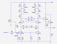
For those curious about the previous version, based on an ECO (Emitter Coupled Oscillator), here it is:
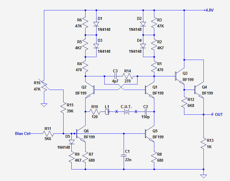
I find it intellectually more satisfying than the current version, but unfortunately, it cannot cope well with "dead" capacitance across the Xtal terminals.
C3 compensates for the fixtures and test connectors, but cannot be made much larger without dumbing down the VHF capabilities.
This oscillator uses the same bias generator as the other one.
Attachments
One important point: even if the frequency-meter is perfectly calibrated, the displayed frequency can be somewhat different from what the crystal is supposed to deliver.
The tester has no way to know in which oscillator the crystal was to be used, and the mode, load capacitance, etc. will generally be quite different.
In general, VHF crystals will be overloaded and read low, and for VLF crystals, the situation will generally be reversed, but not for very small, watch crystals for which the capacitance will also be higher than normal.
Also to keep in mind: overtones crystal will always oscillate at their fundamental, which will be 3 or 5 times lower than what is printed on the case.
Last edited:
One last thing: it probably goes without saying (but being totally explicit is even better) the tester will force anything that resembles (or is) a series tuned circuit into oscillation.
That includes actual L-C resonant circuits, transmission line resonators, and all of the electromechanical resonators, like piezo resonators:
That includes actual L-C resonant circuits, transmission line resonators, and all of the electromechanical resonators, like piezo resonators:
Attachments
")
- Status
- This old topic is closed. If you want to reopen this topic, contact a moderator using the "Report Post" button.
- Home
- Design & Build
- Equipment & Tools
- Universal Xtal tester