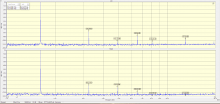
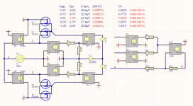
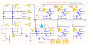
THD Out=5Vmax 10Vpp F=1.6KHz
------------------------------------------
Output ---- 0° - 0,000 004%
Output -- 90° - 0,000 011%
Output - 180° - 0,000 022%
Output - 270° - 0,000 011%
------------------------------------------
Output ---- 0° - 0,000 004%
Output -- 90° - 0,000 011%
Output - 180° - 0,000 022%
Output - 270° - 0,000 011%
Attachments
There are no filters.Looks like you accepted the idea of filtered harmonics on the generator output to good use. Now we need a THD or FFT measurement to back up those SIM numbers.
THx-RNMarsh
Attachments
If I'm interpreting your spectra correctly, the upper one comes from the channel without the notch filter and the post filter amplification. If this is so, what is the reason for dividing the THD of 0.051% by 10000, i.e. lowering it by 80dB?THD=0.051/10000----0.000 0051% -146db
Regards,
Braca
I like the circuit, in particular the zero-ripple AGC and its Fet active linearization, but I don't see how it is possible to reach a THD level of 40ppb with these opamps.
Sure, the NE5534's are good and trustworthy workhorses, but their native THD level is at least 10 to 100 times worse than that, and I see no tricks that could overturn that, unlike the one used in the output circuit (and I doubt that this compensation trick alone could suffice anyway).
So, what's the secret?
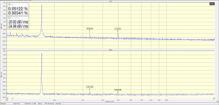
Top channel "L" with Firtra (0.051%)If I'm interpreting your spectra correctly, the upper one comes from the channel without the notch filter and the post filter amplification. If this is so, what is the reason for dividing the THD of 0.051% by 10000, i.e. lowering it by 80dB?
Regards,
Braca
Bottom channel "R" (0.0034%) Direct to see the THD of the sound card that are low enough compared to the measured.
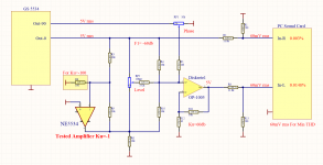
The generator does not use the frequency correction C24, C26, S31 is not needed.
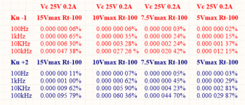
Correct measurement of THD for NE5534.
THD = 0.000 015 Rt=3к Ku=-1 Uout=5Vrms
THD = 0.000 240 Rt=1к Ku=-1 Uout=5Vrms
Correct measurement of THD for LT1115
THD = 0.000 008 Rt=3к Ku=-1 Uout=5Vrms
(As an integrator generates)!!
Correct measurement of THD for Diskreje OP1005
THD = 0.000 8 Rt=3к Rt=1k Ku=+1000 Uout=5Vrms
Equivalent to
THD = 0.000 000 8 Rt=3к Rt=1k Ku=1 Uout=5Vrms
Without it, measuring the above amplifiers cannot be done correctly.
Correct measurement of THD for NE5534.
THD = 0.000 13 Rt=5к Ku=-100 Uout=5Vrms
THD = 0.001 30 Rt=1к Ku=-100 Uout=5Vrms
Correct measurement of THD for NE5532.
THD = 0.000 4 Rt=5к Ku=-100 Uout=5Vrms
THD = 0.004 0 Rt=1к Ku=-100 Uout=5Vrms
Correct measurement of THD for NE5534.
THD = 0.000 015 Rt=3к Ku=-1 Uout=5Vrms
THD = 0.000 240 Rt=1к Ku=-1 Uout=5Vrms
Correct measurement of THD for LT1115
THD = 0.000 008 Rt=3к Ku=-1 Uout=5Vrms
(As an integrator generates)!!
Correct measurement of THD for Diskreje OP1005
THD = 0.000 8 Rt=3к Rt=1k Ku=+1000 Uout=5Vrms
Equivalent to
THD = 0.000 000 8 Rt=3к Rt=1k Ku=1 Uout=5Vrms
Without it, measuring the above amplifiers cannot be done correctly.
Correct measurement of THD for NE5534.
THD = 0.000 13 Rt=5к Ku=-100 Uout=5Vrms
THD = 0.001 30 Rt=1к Ku=-100 Uout=5Vrms
Correct measurement of THD for NE5532.
THD = 0.000 4 Rt=5к Ku=-100 Uout=5Vrms
THD = 0.004 0 Rt=1к Ku=-100 Uout=5Vrms
Attachments
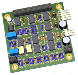
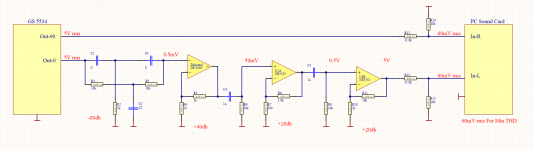
I noticed 10K resistors on the positive input of U10 and U11. I would expect that to limit the noise performance even with the 1U bypass. And they would definitely not be optimum for the LT1115.
The way you are listing the distortions is different from common practice which can be confusing here. The typical practice is in percent (moving the decimal point over 2) but I prefer dB which is much more manageable when dealing with very low distortions. I get googly eyed with too many zero's.
I like the 4 phase rectifier. I used an LM339 quad comparitor to do the same. It doesn't need the diodes and removes the diode drop.
")
So, what's the secret?
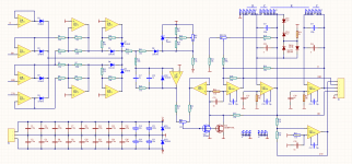
There are lots of confusing things here, SPICE macro models don't typically model distortion. What are actual measurements here vs simulations? I see a twin tee labeled -80dB but in a simulator you can trim it to what ever you want and the attenuation of the harmonics is not uniform.
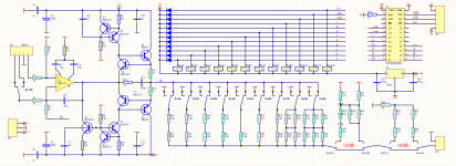
@Kay Pirinha, The oscillator uses a "state variable" topology. For an excellent primer, see the link below.
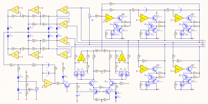
The incentive for the four different phases is to develop a "4-phase rectifier" to provide a more-easily filtered indication of oscillator amplitude to the amplitude stabilization control. Four phases combine to provide lower ripple and the the higher harmonic content is easier to filter. The HP339A oscillator uses only a single phase, diode envelop detector. Mr. Cordell's design below uses 2 phase detection, and I recall one of his posts suggested 4-phase for better suppression of amplitude ripple. Any ripple introduces distortion into the generator output.
http://www.cordellaudio.com/instrumentation/thd_analyzer.pdf
I believe the presented design has many very clever features. But like other members, I regret that I must take issue with some of the initial projections of harmonic levels. I'm a little confused. Have some of the projections now been revised? Intuition tell me that this instrument may still have admirable performance.
Regards to SandyTodorov1.
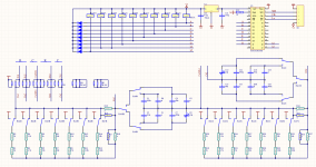
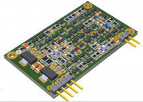
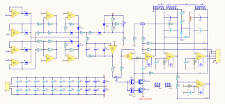
This is just a conceptual design for now.
The latest corrections are optimized for low noise and THD.
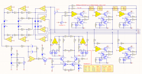
8 phase regulator allows a simple and inexpensive solution to the AGC filtering problem.
Contemporary 5534s operate without a correction capacitor as integrators.
Because of this, they have 3-4 times less distortion than 5532.
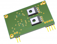
Buffering eliminates the THD problem for loads below 3k and will allow you to get a low noise level at the output.
The use of two sequentially connected JFETs reduces 2 THDs at a level of 25mV (2x12.5mV)
The simultaneous and counter phase adjustment of the positive and negative feedback decreases twice the required level.
The AGC signal is within +/- 0.5V as at 0V level THD imported by JFET are aiming at 0.Идеята на проекта
It is natural to use modern amplifiers OPA1612, LT1115. This will make the output noise even smaller.
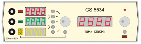
The idea of the project is simple and cheap but at least 5-10 times better generator than ShibaSoku AG15C example.
The latest corrections are optimized for low noise and THD.
8 phase regulator allows a simple and inexpensive solution to the AGC filtering problem.
Contemporary 5534s operate without a correction capacitor as integrators.
Because of this, they have 3-4 times less distortion than 5532.
Buffering eliminates the THD problem for loads below 3k and will allow you to get a low noise level at the output.
The use of two sequentially connected JFETs reduces 2 THDs at a level of 25mV (2x12.5mV)
The simultaneous and counter phase adjustment of the positive and negative feedback decreases twice the required level.
The AGC signal is within +/- 0.5V as at 0V level THD imported by JFET are aiming at 0.Идеята на проекта
It is natural to use modern amplifiers OPA1612, LT1115. This will make the output noise even smaller.
The idea of the project is simple and cheap but at least 5-10 times better generator than ShibaSoku AG15C example.
Attachments
This is just a conceptual design for now.
It is natural to use modern amplifiers OPA1612, LT1115. This will make the output noise even smaller.
The idea of the project is simple and cheap but at least 5-10 times better generator than ShibaSoku AG15C example.
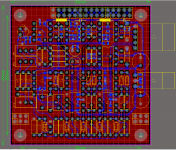
Lets build it, please. Your design maybe ultra low and we should develop it further and make pcb and test/measure it.
THx-RNMarsh
- Home
- Design & Build
- Equipment & Tools
- low Distortion Oscillator GS 5534-8 (NE5534)