Sandy:
There are a number of interesting ideas in your design.
First, let me reiterate the old story that simulations are only as good as the models and the models are not that good. Do not be surprised if the distortion is 20 dB worse or better than the simulation. There are many effects that are not in models that pop up below -120 dB.
Second, have built the multiphase amplitude detector, it works, but. . . Good part is that its faster settling since there are more pulses to get the peak value. However the 4 phases will not have the same amplitude so you still have ripple and now its at HD4. There are some tricks for cancelling that effect in the Amber 3501 oscillator. It's worth a look.
Ultimately the sample and hold seems to work the best and avoids integration. DavidA's concept of using an ADC as a sampler is great. I think tweaking it with a multiplying DAC and a micro-based PID controller could be the best solution since it would not depend on a nonlinear element being linearized. A second multiplying DAC could be used for tuning.
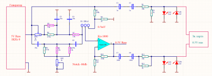
Third, noise. The dominant noise will be opamps and the resistances around them. If you start with a very low noise opamp (AD797, LME49990 (unfortunately EOL) or LT1115) the resistive part of the tuning should be lower than 50 Ohms. That's probably impractical but keeping them as low as possible while still meeting the device distortion and operating at the highest practical voltage helps a lot. Comparing the 600 Ohm and the 50 Ohm output of a KH4400 on a suitable analyzer shows the limitations of 600 Ohms. Higher voltages help since the noise is constant.
I have a Shibasoku 590AR and I'm pretty familiar with it. It is better than -120 dB THD. However, I think its AGC is the limitation, particularly the analog multiplier. I tried swapping several (it's socketed) and saw small differences but I suspect it could be better still. I have not traced that circuit out and it's not obvious how it works from simple inspection so other than tweaking the input offsets nothing else has made a difference. The bias is fixed and I don't think an issue anyway.
I use Victor's oscillators as a reference and can get -120 dB THD+N between 2-3V on the Shibasoku 725's. I'm told this is the current state of the art for this. I have not seen verifiable claims of better. My Radiometer CLT-1's can hit -170 dB HD3 but they are quite unique and not very useful for general measurements.
There are a number of interesting ideas in your design.
First, let me reiterate the old story that simulations are only as good as the models and the models are not that good. Do not be surprised if the distortion is 20 dB worse or better than the simulation. There are many effects that are not in models that pop up below -120 dB.
Second, have built the multiphase amplitude detector, it works, but. . . Good part is that its faster settling since there are more pulses to get the peak value. However the 4 phases will not have the same amplitude so you still have ripple and now its at HD4. There are some tricks for cancelling that effect in the Amber 3501 oscillator. It's worth a look.
Ultimately the sample and hold seems to work the best and avoids integration. DavidA's concept of using an ADC as a sampler is great. I think tweaking it with a multiplying DAC and a micro-based PID controller could be the best solution since it would not depend on a nonlinear element being linearized. A second multiplying DAC could be used for tuning.
Third, noise. The dominant noise will be opamps and the resistances around them. If you start with a very low noise opamp (AD797, LME49990 (unfortunately EOL) or LT1115) the resistive part of the tuning should be lower than 50 Ohms. That's probably impractical but keeping them as low as possible while still meeting the device distortion and operating at the highest practical voltage helps a lot. Comparing the 600 Ohm and the 50 Ohm output of a KH4400 on a suitable analyzer shows the limitations of 600 Ohms. Higher voltages help since the noise is constant.
I have a Shibasoku 590AR and I'm pretty familiar with it. It is better than -120 dB THD. However, I think its AGC is the limitation, particularly the analog multiplier. I tried swapping several (it's socketed) and saw small differences but I suspect it could be better still. I have not traced that circuit out and it's not obvious how it works from simple inspection so other than tweaking the input offsets nothing else has made a difference. The bias is fixed and I don't think an issue anyway.
I use Victor's oscillators as a reference and can get -120 dB THD+N between 2-3V on the Shibasoku 725's. I'm told this is the current state of the art for this. I have not seen verifiable claims of better. My Radiometer CLT-1's can hit -170 dB HD3 but they are quite unique and not very useful for general measurements.
I have a Shibasoku 590AR and I'm pretty familiar with it. It is better than -120 dB THD. However, I think its AGC is the limitation, particularly the analog multiplier. I tried swapping several (it's socketed) and saw small differences but I suspect it could be better still.
Which one? I used the SSM part because it did better than the general purpose multipliers. We got -130dB but published -120dB because one can't expect folks to swap and fiddle to get something to work.
Your experience is correct, we had an intern many years ago make a map of distortion after trim of Gilbert style multipliers and if you went through enough of them you might get a serious improvement.
They used an MC1495 http://www.onsemi.com/pub/Collateral/MC1495-D.PDF . I bought a handful and swapped them. Left the best performing in but it was not a big difference. Trimming would maybe help but with no docs I have been really reluctant to do anything that may backfire. There are a lot of parts in that circuit.
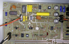
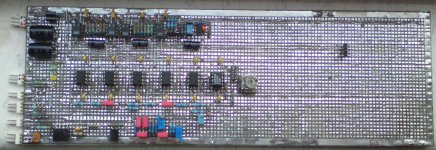
Attachments
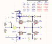
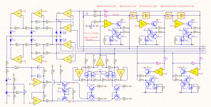
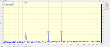
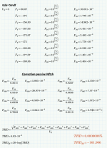
Those are real measurements? They are around .0008% or -142 dB if I understand your notes in the drawing. They are pretty good. How did you measure them? it would be interesting to see the magnitude of the ripple at the output of U4A.
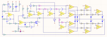
The stacked Jfet idea seems something that could be easily implemented on existing designs.
The stacked Jfet idea seems something that could be easily implemented on existing designs.
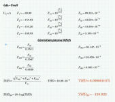
These are not real measurements, but just a simulation of what the AGC chain carries.
Putting two JFETs reduces the amplitude twice to each and then THD.
The measurements are ahead. And they will be most likely at low THD because deduction will be lower than 1% AGC values.
A simple and obvious solution I do not know why no one has ever used it. Thinking is not an easy job.
-----------------------------------------------------------------
Sorry for bad English, but to translate from the richest language to the poorest is complicated.
Attachments
Hi Sandy,
You language skills are admirable.")
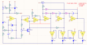
I think your ideas are very intriguing--- not only the series connected FETs, but also the notion of a "balanced" differential design. My head hurts when I try to think about how the four FETs will interact, especially since they won't have identical characteristics.
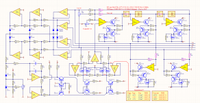
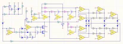
Unsolicited advice: If you have the luxury of already owning a distortion analyzer, I would suggest bread-boarding the FET network before undertaking the layout of the entire circuit. i.e. circuitry from U4 pin 1 through U7 output, with the "90 degree" node driven as the test input. Of course low distortion is desirable for all control voltage inputs. From a control loop perspective, perfect linearity of control characteristics probably isn't unduly important, but "dead zones" would be undesirable. Any hysteresis would be a problem, though I don't foresee that.
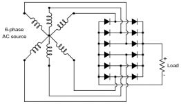
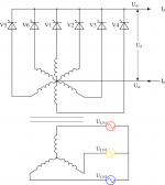
I also admire your 8-phase rectifier. I'm not sure synthesizing 45 degrees from 0 and 90 would ever have occurred to me.
Good luck!
You language skills are admirable.
I think your ideas are very intriguing--- not only the series connected FETs, but also the notion of a "balanced" differential design. My head hurts when I try to think about how the four FETs will interact, especially since they won't have identical characteristics.
Unsolicited advice: If you have the luxury of already owning a distortion analyzer, I would suggest bread-boarding the FET network before undertaking the layout of the entire circuit. i.e. circuitry from U4 pin 1 through U7 output, with the "90 degree" node driven as the test input. Of course low distortion is desirable for all control voltage inputs. From a control loop perspective, perfect linearity of control characteristics probably isn't unduly important, but "dead zones" would be undesirable. Any hysteresis would be a problem, though I don't foresee that.
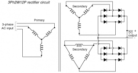
I also admire your 8-phase rectifier. I'm not sure synthesizing 45 degrees from 0 and 90 would ever have occurred to me.
Good luck!
......I also admire your 8-phase rectifier. I'm not sure synthesizing 45 degrees from 0 and 90 would ever have occurred to me....
It is "everyday" in an obscure corner of electrical engineering. 3-Phase power is good stuff as-is. But for some DC applications it makes sense to take cross-connections from available 3-phase to get 6-phase power. I have seen 12-phase rectifiers. The DC is real smooth without any filtering. The same thinking works for 2- and 4-phase systems... the in-between connections give the in-between phase. (Not for US type household "2-phase" which is really single-phase; the center-tap does not give any interesting phase angle.)
Attachments
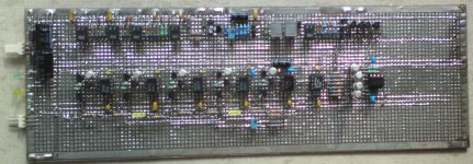
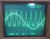
It's not Christmas and miracles happen!
Works more than well.
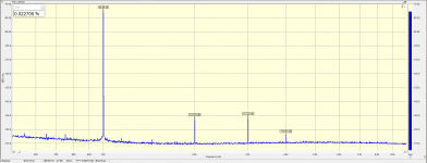
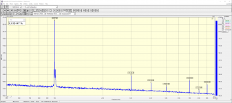
I did some initial measurements.
The biggest influence is the change of Cf1 10% change wants 0.1% of AGC (10mV) at 10Vmsx (7.07Veff) signal at the output.
A 0V nozzle at the U7 output does not float more than +/- 1mV for a few hours. Which preaches the extraordinary THD!
75mV differences in 8 phase rectifier are due to not the R12 / 13 precision is not exactly 7.07k
Works more than well.
I did some initial measurements.
The biggest influence is the change of Cf1 10% change wants 0.1% of AGC (10mV) at 10Vmsx (7.07Veff) signal at the output.
A 0V nozzle at the U7 output does not float more than +/- 1mV for a few hours. Which preaches the extraordinary THD!
75mV differences in 8 phase rectifier are due to not the R12 / 13 precision is not exactly 7.07k
Attachments
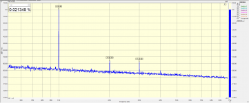
Try dropping the level both in and out of the soundcard. Typically they are much better starting at -6 dBFS and you get the best distortion at -15 dBFS or so. You could get 10 to 15 dB improvement in distortion.
Led's are not as benign as they might be. They have a pretty soft knee and significant reverse leakage. A good signal diode in series can provide significant additional isolation which is important when the source Z is high (greater than 50 Ohms). In extream cases, there are tricks for using JFETS but I hope that stuff isn't needed here. Otherwise the protection is a good idea since most soundcards are fragile and a PITA to fix.
Led's are not as benign as they might be. They have a pretty soft knee and significant reverse leakage. A good signal diode in series can provide significant additional isolation which is important when the source Z is high (greater than 50 Ohms). In extream cases, there are tricks for using JFETS but I hope that stuff isn't needed here. Otherwise the protection is a good idea since most soundcards are fragile and a PITA to fix.
I did 2 times the higher AC voltage on the JFET but I put 2 JFETs with one JFET THD are more, apparently outperforming those of the operating amplifiers.
But with 2 JFETs, they were fine.
With RP2, a virtually second harmonic is set to 0.
However, I can not decide how to best manage JFET, so that this regulation does not change the Ugs constant voltage.
Here is how, but there were strong 5,7,9 which before some of the experiments were gone.
We will see if it is from the installation or the influence of the two operating U1s in one housing.
Attachments
- Home
- Design & Build
- Equipment & Tools
- low Distortion Oscillator GS 5534-8 (NE5534)