I have a question about Behringer UMC204HD because I want to buy one. Is it possible to make frequency measurement in ARTA with device's microphone preamp? What I found there's no mic preamp output which should be connected to UMC204HD line input. What if I need to connect like on this scheme: http://www.mh-audio.nl/images/measurement/AcousticMeasurementSetup2ch.gif Is it possible? or do I need external microphone preamp?
It appears that the inputs are switchable independently between mike, like and instrument (high level hi-Z single ended). You should be able to configure per the drawing with a resistor divider and a cable. if your amp is not BTL then a simple cable with resistors into the left channel 1/4" connector set to instrument would work pretty well. Use lower values for the resistors (9.1K and 1K for an approx 10:1 divider that is low Z and should not need any trim cap for frequency compensation.
Left and right inputs are fully independently configurable.I have a question about Behringer UMC204HD because I want to buy one. Is it possible to make frequency measurement in ARTA with device's microphone preamp? What I found there's no mic preamp output which should be connected to UMC204HD line input. What if I need to connect like on this scheme: http://www.mh-audio.nl/images/measurement/AcousticMeasurementSetup2ch.gif Is it possible? or do I need external microphone preamp?
So you can use the built in XLR Mic preamp on the left input and use a line level signal on the right input and adjust the gain separately. No separate preamps needed.
When I do dual channel measurements like that shown in the diagram I don't use a resistive divider I actually use a balanced microphone transformer configured in step down mode to sample the amplifier output, provide galvanic isolation (completely eliminates earth loops) and step the voltage down to within line input limits and then use the front right input in balanced line level mode.
However if you want to use a resistive divider this can be done too - if you want to avoid some slight 2nd harmonic distortion in the measurements due to driving the balanced input with an unbalanced signal you can use the insert input on the rear to bypass the preamp entirely as I described ealier in the thread, as the insert input takes an unbalanced line level signal.
Left and right have separate TRS insert sockets so you can use the right channel insert input without affecting use of the left channel mic preamp.
If you use the insert input you lose the gain adjustments on the front panel for that channel so choose your resistive divider values wisely.
Last edited:
I guess this is a good place to ask what is latest greatest USB soundcard for measuring fft using current pc software. I have several software analyzers and they all agree on loopback distortion - bandwidth etc. (Both mac and windows)
Currently using Steinberg UR-22 and UR22II but ready to try something new.
I did lots of searches using google and "site:diyaudio soundcard usb fft measure"
Not much is there except focusrite etc but output spec is high thd.
I don't want to get back into the proprietary html-linux-ftp thing so staying with USB.
I'm ok with using averging to fix usb jitter.
Thanks
I Have a scarlett 2i4 works great except that the maximum output voltage that I can achieve is about 1.2v RMS.
Distortion in a loopback test is about 0.0025% at 1k
Im using Visual Analyser software.
You may want to look at this to.
QA401 Audio Analyzer
– QuantAsylum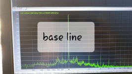
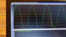
Distortion in a loopback test is about 0.0025% at 1k
Im using Visual Analyser software.
You may want to look at this to.
QA401 Audio Analyzer
– QuantAsylum


?? The QA401 works with its own software and is basically plug and play. If you want to use the hardware with different software you need to add one ASIO driver. It is more expensive but I think a real value.
Try the soundcard distortion at -10 to -15 dBFS to get the best distortion performance.
Try the soundcard distortion at -10 to -15 dBFS to get the best distortion performance.
?? The QA401 works with its own software and is basically plug and play.
I'm interested in the QA401 what's is frequency range looks like the -3db point is 70khz.
What options are there for 20khz THD measurements because this can only give you the 3 harmonic at best.
If you have an amplifier with the usual design bandwidth of 20hz to 20khz then the only way to test the THD at 20khz is to provide the measurement device or software with a say a 20khz sing wave signal and then it will caculate how accurately that sine wave is formed. If it can only use 2 or 3 harmonics then the results won't be accurate. Just look at the THD formula. It compares the harmonics to the fundamental frequency.How are >70KHz distortion products relevant in audio?
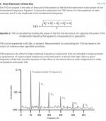
I understand that but do not understand why it is relevant.
Its probably not relevant from a hearing perspective, but from a audio amplifier design perspective where you maybe chasing low distortion numbers. How else can you compare one design or topology against another unless you use specialised measuring equipment with a high testing bandwidth.
Its not hard to design a amplifier with 0.001% Distortion at 1K into 8ohms but to do it at 20khz is alot harder. So we need some way of measuring it and for this we need the subsequent harmonic frequencies. Most ltspice simulations will go out to the 10 harmonic.
I'm interested in the QA401 what's is frequency range looks like the -3db point is 70khz.
What options are there for 20khz THD measurements because this can only give you the 3 harmonic at best.
Its actually god to almost 96K. A better and more demanding test would be a 2 tone IM at 19 KHz and 20 KHz. The FFT would be able to show the interactions. Testing under load will show if there are significant HF problems that can fold down into the audio band.
If you have an amplifier with the usual design bandwidth of 20hz to 20khz then the only way to test the THD at 20khz is to provide the measurement device or software with a say a 20khz sing wave signal and then it will caculate how accurately that sine wave is formed. If it can only use 2 or 3 harmonics then the results won't be accurate. Just look at the THD formula. It compares the harmonics to the fundamental frequency. View attachment 801152
Depending on how much work you want to do and how much money you want to spend, you can get SAR ADC evaluation boards and design your own front end to get out to the MHz range. You'll have to live with their limited software, but the LT version (PScope) does do FFTs of various lengths, has a few windows you can choose from, and can save the FFT data.
I've thought about making a USB ADC with a fast ADC, but not sure I'll ever get the time. If you exceed 768 kSPS you are basically looking at having to write custom software and most likely using a Cypress or FTDI FIFO to USB chip with their drivers and APIs. I believe this is what QA does (Cypress).
I Have a scarlett 2i4 works great except that the maximum output voltage that I can achieve is about 1.2v RMS.
Distortion in a loopback test is about 0.0025% at 1k
Im using Visual Analyser software.
Are you using any protection on the inputs?
I just ordered a 2i4 for $200AUD, which is the same price as the 2i2.
Are you using any protection on the inputs?
I just do the math.
I did alot of testing before I understood the best way to set one of these up for lowest distortion.
It's actually very easy once you know how.
I made up a little attunuation circuit to attunuate the amplifiers output voltage down to 1v RMS.
I also have some jumpers that allow me to temporarily simulate the input impedance of the scarlett before I actually plug in. So I can test and confirm my math is correct.
I might make a YouTube video at some point. Just so busy at the moment.
One thing to note. The input impedance of the scarlett is about 13,437 ohms
Here are some calculation examples of a attunuation resistor.
V=Srt(PxR) and P=V^2 x R
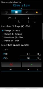
So for 1 watt RMS into 8.1 ohms we need to drop 2.846v RMS across the resistor.
For 10 watt RMS into 8.1 ohms we need to drop 9v RMS across the resistor.
For 50 watt RMS into 8.1 ohms we need to drop 20.12v RMS across the resistor.
For 100 watt RMS into 8.1 ohms we need to drop 28.46v RMS across the resistor.
For 150 watt RMS into 8.1 ohms we need to drop 34.85v RMS across the resistor.
Calculate Vin using the voltage divider calculation
R1 is the output impedance of the amp. (Example amp = 597m ohms)
R2 is the load resistor.
And Vout is the required voltage from above.
--------
Then use The Vout voltage to calculate the attenuation resistor. Vout will now become Vin and using the voltage divider calculator again.
Example.
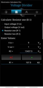
For 10 watts. Vin will now be 9v (Vout from above).
We need to Calculate R1
R2 will be the input impedance of the scarlet (13,437.5 ohms) and Vout will be 1v RMS which is 0db.
R1= 107.5 K ohms
Note
0.316227766v RMS = -10db
1V RMS = 0db
3.1622v = 10db
------------'
Don't forget to calculate the wattage through the attenuation resistor. P=V^2 x R where V is the voltage dropped across the attenuation resistor.
- Home
- Design & Build
- Equipment & Tools
- USB Audio interface for measurement