Hello all,
The AT2380 design is now finished and all work as a charm.
I made some modifications on the original design,and i add it
to the rev2 of schematic and a new PCB for a group buy.
Fully updated schematics and manual will be posted.
I started to make the promised video, but not yet ready.
Will come very soon...
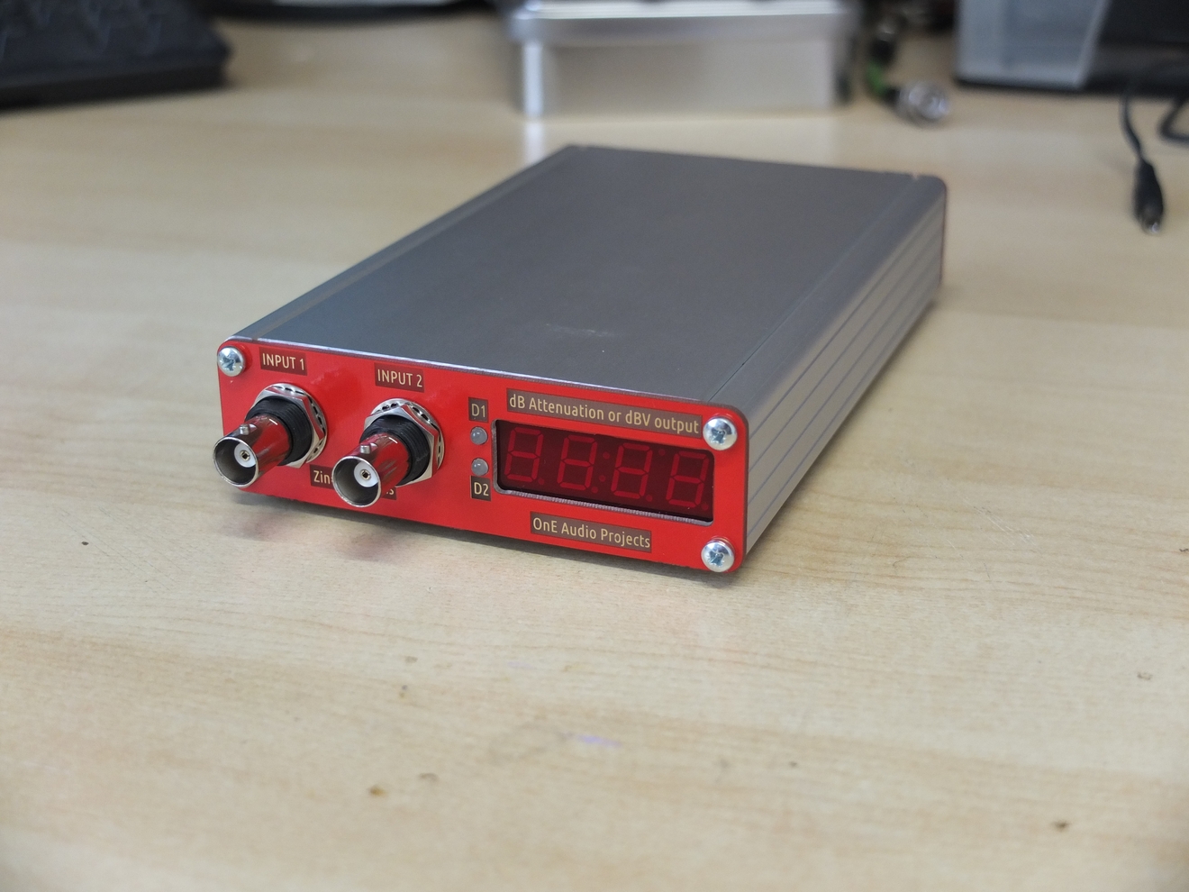
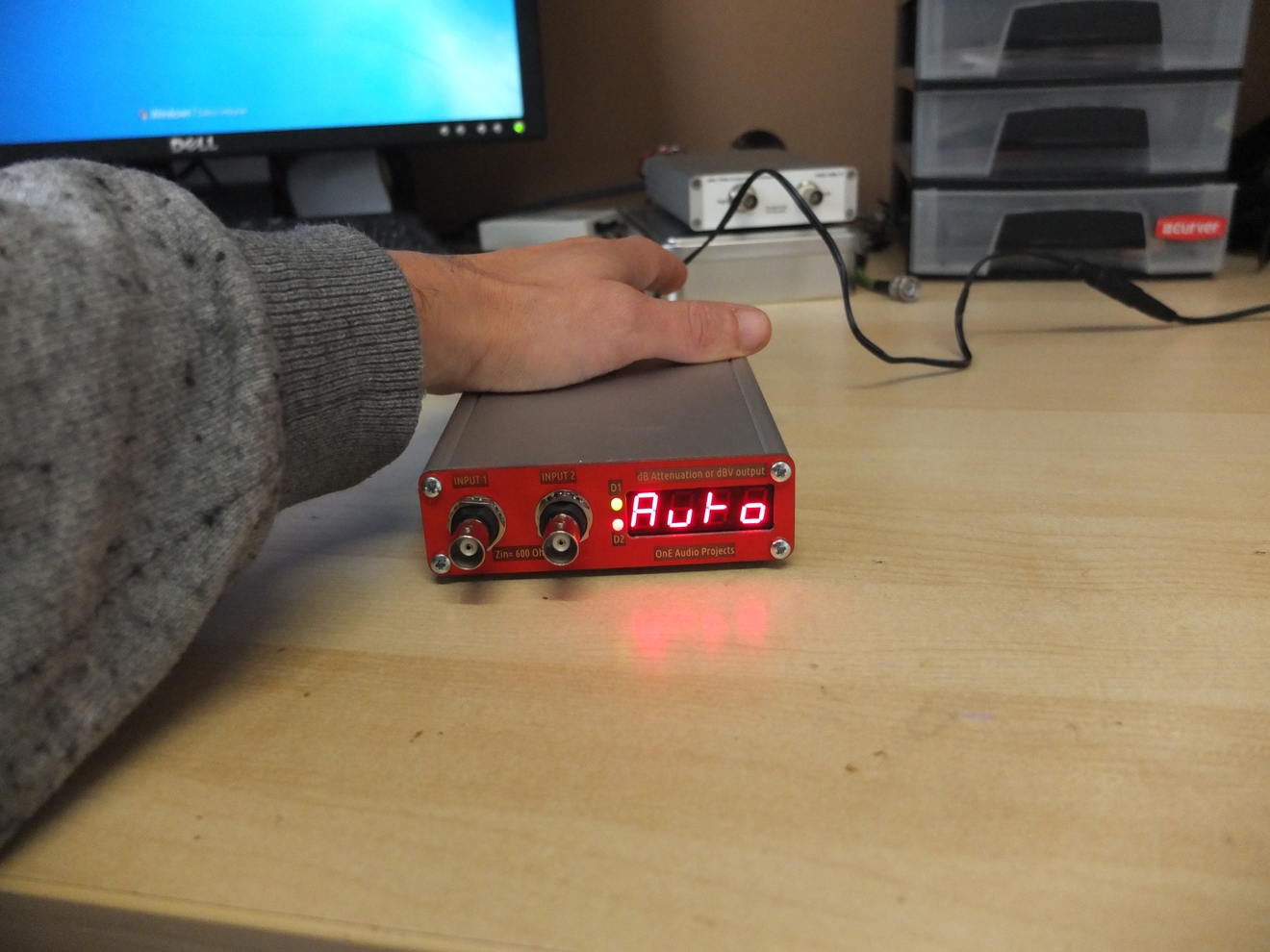
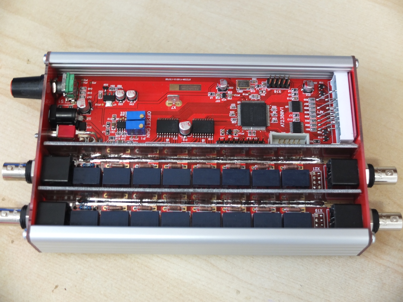
Some pictures below of the finished prototype unit ( before upcoming movie...):
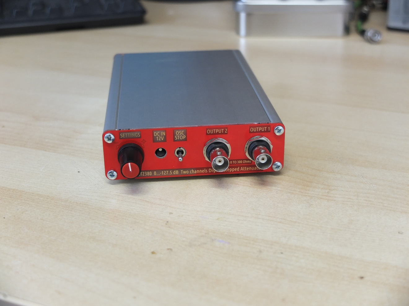
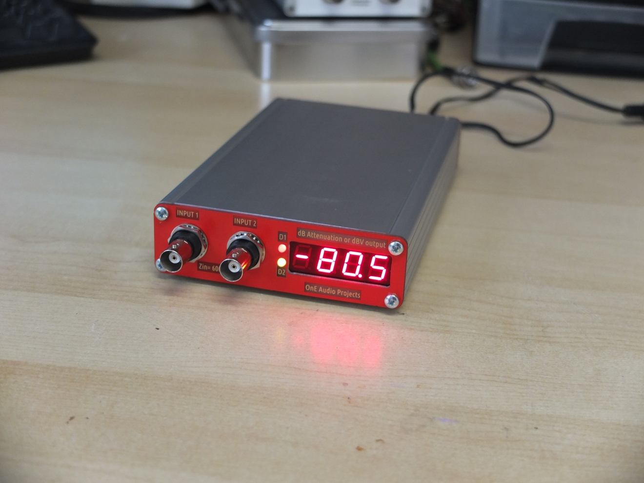
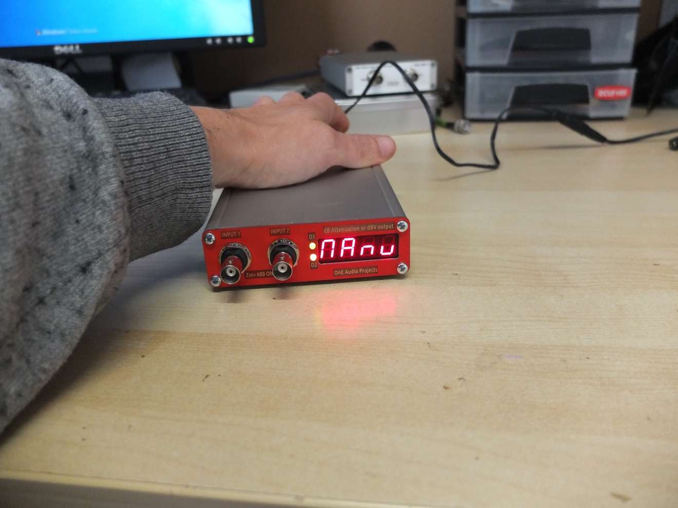
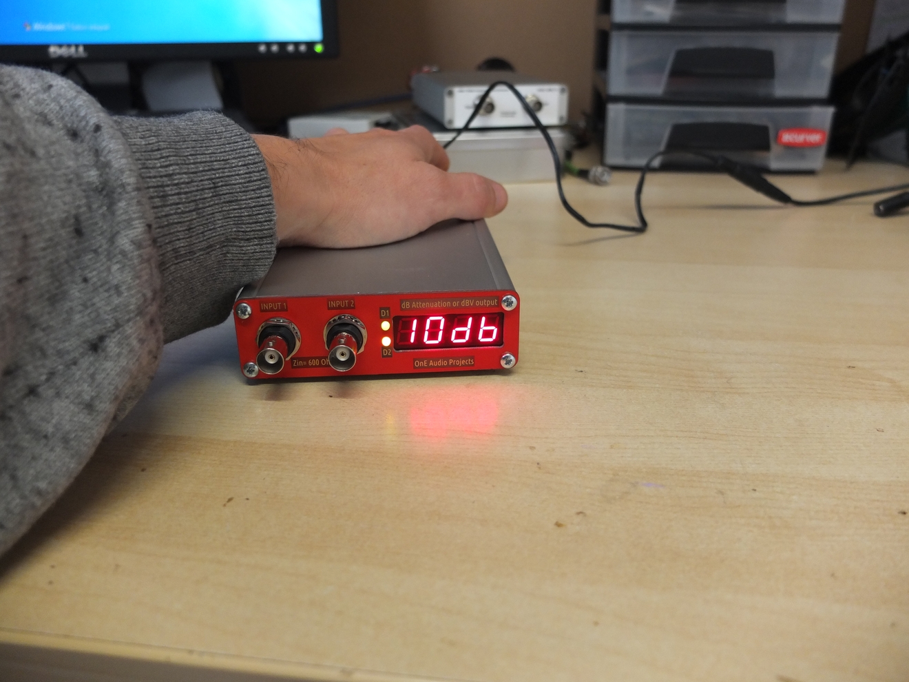
Note that I've verified successfully the attenuation level
up to -120dB by using 60dB external post amplifier.
If there is some people that want to build the project,
i can open a wiki page to make a preorder list for the bare PCB.
Comment welcome.
Regards.
Frex
The AT2380 design is now finished and all work as a charm.
I made some modifications on the original design,and i add it
to the rev2 of schematic and a new PCB for a group buy.
Fully updated schematics and manual will be posted.
I started to make the promised video, but not yet ready.
Will come very soon...
Some pictures below of the finished prototype unit ( before upcoming movie...):
Note that I've verified successfully the attenuation level
up to -120dB by using 60dB external post amplifier.
If there is some people that want to build the project,
i can open a wiki page to make a preorder list for the bare PCB.
Comment welcome.
Regards.
Frex
Hi Frex,
I'm in for one")
JC
Hello all,
If there is some people that want to build the project,
i can open a wiki page to make a preorder list for the bare PCB.
Comment welcome.
Regards.
Frex
I'm in for one
JC
Video presentation.
Hello,
I just finished the two presentation videos of the AT2380, you can look them here :
AT2380 DIY 2 channels digitally controlled stepped attenuator- Introduction video Part 1/2
AT2380 DIY 2 channels digitally controlled stepped attenuator- Introduction video Part 2/2
Please, be indulgent if my English is not top notch !
(Note that in second video, i made a mistake, at time 3.39 you must ear
"the difference between effective OUTPUT signal and dBV setting for the output". )
Frex
Hello all,
I post the final revision 2.0 of the schematic now.
I update also the first post of the thread with all new data.
You can download it below :
AT2380V2_sch.pdf
The corresponding PCB is nearly finished, and i add some
improvement from prototype.
I also wrote the user manual of the attenuator to explain how
to use it. It include also an extended measurements report made in my lab on the prototype.
You can download it below :
AT2380v2_Manual_v0.pdf
The complete bill of material file with price list will come too.
I will open the wiki group-buy page on next week-end.
Frex
Hi Frex,
first i want to congratulate you on this nice project. Have followed your other projects and really admire your skill and work.
A multichannel attenuator is attractive for those looking for analog volume/level control after their multichannel DAC for active speakers.
I was looking for such a device in my 4way active speaker.
Hello,
Thank you very much diyaudnut.
As i answered, you can use the attenuator for multichannel purpose.
If attenuation level is same for all channel, the same logic can drive all attenuator boards
so that reduce bom cost because all part can be mounted on only one PCB.
I must recognize that i designed it mainly for measurements.
Frex
Hello all,
I opened now the PCB groupbuy for the AT2380v2 project.
I started a new thread in GroupBuy section of the forum,
all detail can be found on it, the link is here :
AT2380v2 2Ch Digitally controlled Stepped Attenuator
Frex
I opened now the PCB groupbuy for the AT2380v2 project.
I started a new thread in GroupBuy section of the forum,
all detail can be found on it, the link is here :
AT2380v2 2Ch Digitally controlled Stepped Attenuator
Frex
Hi Frex,
looking forward to the GB.
I understand you designed this primary as a measurement support device.
Its great that it will also work great as a passive volume control with exceptional, almost wire like performance.
Wonder how easy it would be to make the I/O connector XLR for volume control application.
Also, for multichannel applications, can the boards be stacked and a single control section driving the boards. Is this doable with the current set of boards.
thanks
ello diyaudnut,
You can easily use the AT2380 with symmetric signal, i even designed the unit for this !
The 2 channels can be use for each positive and negative part of the signal.
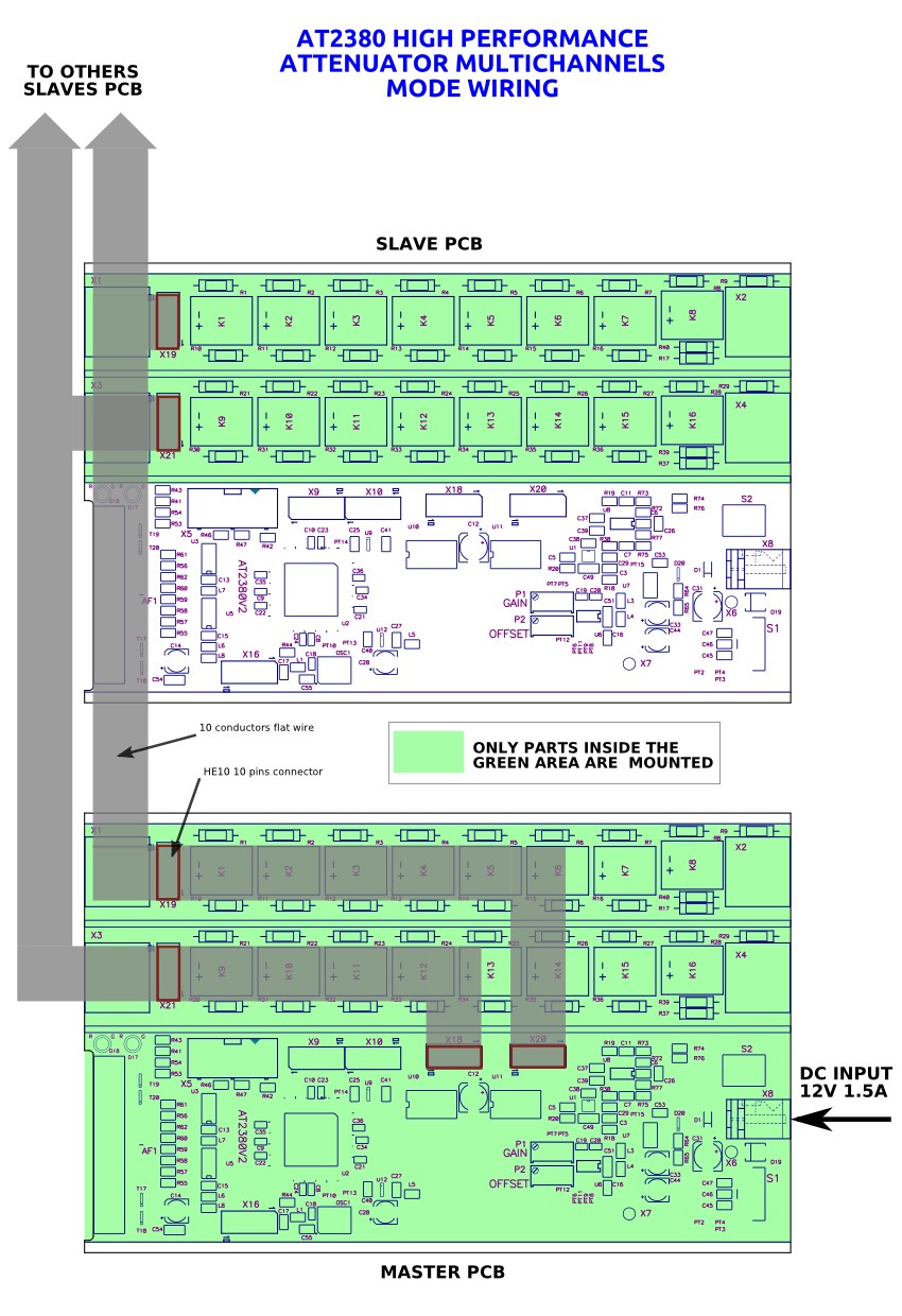
It is possible to use a stack of PCB that can be driven by only one (a master) for any multichannel purpose.
In fact, a single "master" board can drive 5 others AT2380 attenuator relays without problem.
For this It is only need to make a longer flat wire that would be connected to all attenuators PCB.
Because the main PCB will drive all relays of 6(5+1) PCB's, the maximum
current could reach about 1.25A. The power supply must be selected accordingly.
Of course only the master PCB will require the digital section,
there would be only the attenuator parts in others (slave) PCB's.
Note also that all channel will have same attenuation.
Frex
You can easily use the AT2380 with symmetric signal, i even designed the unit for this !
The 2 channels can be use for each positive and negative part of the signal.
It is possible to use a stack of PCB that can be driven by only one (a master) for any multichannel purpose.
In fact, a single "master" board can drive 5 others AT2380 attenuator relays without problem.
For this It is only need to make a longer flat wire that would be connected to all attenuators PCB.
Because the main PCB will drive all relays of 6(5+1) PCB's, the maximum
current could reach about 1.25A. The power supply must be selected accordingly.
Of course only the master PCB will require the digital section,
there would be only the attenuator parts in others (slave) PCB's.
Note also that all channel will have same attenuation.
Frex
AT2380 PCB multichannel interconnect
Hello,
To be more clear than all my previous explanation,
I drawed a little illustration to show how interconnect several AT2380 PCB for a multichannel attenuator.
Note that a single board can be used for 2 single-ended channel or one symmetric.
You can dowload the file also HERE as a pdf .
I hope that is clear.
Frex
- Status
- This old topic is closed. If you want to reopen this topic, contact a moderator using the "Report Post" button.
- Home
- Design & Build
- Equipment & Tools
- AT2380v1 // 2 Channels digitally controlled stepped attenuator