Nice,
Auto-nulling and an AM detector you might not use.
The same thing s apply to these that apply to any other electronic thing. Check the capacitors in the power supply. Switch contacts may need to be cleaned. Do not get any liquid of any kind in that large tuning capacitor or any other trimmer capacitor! Clean very carefully.
The tuning knob might be stiff or stuck. Do not force it! There is a nylon coupler that can break if you do. Take the tuning cap knob apart remembering where everything goes. Take pictures. Once you are down to the actual shafts, clean them with solvent, dry completely. After that, apply some fine, single weight machine oil (zero additives!!). Not very much, and you will probably still use too much lubricant. Slip the shafts back into the bearings and work them until they move free and easily. You might have to clean the shafts and relube a couple times. Clean out any excess oil and also from the entrance and exists of the bearings. Reassemble and try it out. The dial should move very smoothly when you are done. You have to push the fine frequency adjust knob in to disengage it from the dial. I'm assuming you cleaned it as well. Use a little grease where the spring pushes on the shaft of the fine tune knob.
These are a pleasure to use compared to any other hand tuned THD meter. Take good care of it.
Do you have the manual for it yet? It can be downloaded from http://bama.edebris.com/manuals/hp/334a/ for no charge. That is a great site for old manuals for test gear. You can also look at 334A Distortion Analyzer [Obsolete] | Keysight (formerly Agilent?s Electronic Measurement) under "Document Library".
-Chris
Thanks for the info!
I do have a manual, and there is also a you tube video of a guy showing how to use it.
It is really just a high precision voltmeter with a tunable notch filter. So you put in a signal a some frequency, measure the level, set the filter to eliminate that frequency and measure what's left. Super easy in concept, but I suspect hard to implement in practice!!
Mine seems to be in very good condition, no sticking knobs or wonky shafts...
Hi Scott,
Good to hear. Your's is better than any I've seen. Best clean and lubricate before it does get sticky if you feel confident to do it.
You're right about how it works, and yes, it is difficult to actually put it into practice. Examine the circuit and specs for the HF cut-off point. Then be amazed.
THe very low noise needed to measure tiny voltages means that the power supply health is very important. Short the input terminals and see what you read on the minimum scale.
-Chris
Back when I was a baby engineer, I commented to my boss that HP equipment was so expensive.This was 1977, and I was using a 20 GHz signal generator that cost about $20K back then...He said, matter of factly, that you get what you pay for, and if you want the best, then it was best to pay for HP gear. Always superbly engineered! I recently got a pair of nice Agilent 35 volt bench supplies. I’ll see how they hold up. So far I like them much more than my old BK Precision supply.
I recently rebuilt my old Textronix 2213A scope. The vertical drive was wonky. I found one of the RF transistors in the vertical output stage was cooked, so I found the replacement type and replaced them both. Works great now.. But THEN I found a 1990’s 500 MHz digital sampling scope, with four traces, cursors, frequency counter, etc.. So I am using that now. I’ll ditch the little Tek scope on eBay. I needed the big scope for my digital audio project. Hard to work with 25 MHz clocks when you can barely sync to them, and when you do you can barely see them!
I am surprised by the availability of good used test equipment out there..
Have a happy new year!
Scott
OK, so I sorted out the new board, and finally hooked up the output stage. I powered it up and blew a circuit breaker. Grrr!! I traced the problem to the negative side of the output stage. The positive side works great!
Turned out I had a bad power transistor and two open resistors (the 0.33 ohm and 10 ohm resistors associated with his device) in the negative side of the output. Took a while to find it as it wasn't shorted, but had 1.2K of collector-emitter resistance both ways.. I suspect that was seriously messing up the bias on all the other devices. They all appear to be fine, and all are very close in junction drops, etc.
I have a new transistor on its way, so I hope to have this running this weekend. Then I can clean up the control board (put in fixed resistors for the current source trimmers), and button this beast up!
I need to make three small changes to the board to better fit a capacitor, to better fit the heatsink and output transistors (the heatsink pins were off by about .05 in), and to fit the SMT stabistors Phloodpants found. I'll do another set of 5 boards, and report back with the performance.
I am planning to go back over my collection of 565 amps (I have six of these!), and will replace the control boards in all of them with this new board.
Cheers!
Scott
The base resistor and emitter resistor for the bad transistor were open? That would take it out of circuit, so the amp should work with the remaining 9 transistors unless something else is wrong. Do you know if they popped open before or after you powered up?
Did you locate an authentic 2SB554? They really should be matched as a set, but you can check their matching in-situ, and under load, by checking the RMS AC voltage across the emitter resistors at various power levels. Check for good matching between emitter resistor ohm values or this test is invalid.
To avoid risking any further transistor blowouts while you troublshoot, you could install just one output—something from the junk drawer—and when you've got it working put the originals back. Just take the screws out of the transistors you're not using to disconnect the collectors, or pop out the emitter resistors.
Last edited:
Hi Scott,
Yes, the outputs really have to be matched. I always match them, then check the drops across the emitter resistors to make certain the current is shared equally. You can use MJ15024 and MJ15025. They are fairly inexpensive, but not as well matched unit to unit as the newer MJ21195 and MJ21196. You can also use those, but I haven't tried them yet in an Adcom. While you're at it, replace the driver transistors after that incident. The transistor doesn't have to be completely failed to be damaged. You can guarantee that they have been operated well outside their maximum ratings until the fuse went. It was a race between the outputs and drivers, and the fuse. Even if the fuse comes in first, the drivers have been very stressed.
I know you didn't want to hear this, but replacing the drivers and outputs is the minimum acceptable repair - especially if you are fixing for someone else. You are worth at least that much, so do it right.
-Chris
Sorry, corrrection, parts list location is here...
https://www.dropbox.com/s/odyzrt987bucyed/GFA-565%20parts%20list.xls?dl=0
https://www.dropbox.com/s/odyzrt987bucyed/GFA-565%20parts%20list.xls?dl=0
Thanks Chris.
Hey Scott!
I'm almost finished building up your board. It looks good. I used 100R 0.1% resistors for the locations you measure across. I will match them in pairs and install them. Maybe even today since they arrived last Saturday.
Note that the headers I used are only good for brand new T0-92 parts (signal transistors) as I'm using the augate milled types. If you want to match T0-126 parts, use the normal headers, but the contact with T0-92 parts will be intermittent. That's why I used both on the ones I designed.
If these parts are the most expensive ones, it is a cheap project to build. The 0.1% resistors allow you to get 1% matches or better. Remember that you must allow the parts to settle in thermally. So 5 minutes might be a little short timing. For tail currents 3 mA and above, the settling time is lower and more stable. The actual tail current isn't as important as it is that it is stable and runs pairs at a similar current. The high impedance helps the parts share more naturally too.
I guess if you are looking for coarse matches, you could use normal 5% resistors and a resistor for the tail current. But if you are going to the trouble of matching the transistors, why would you "cheap out" in this way?
-Chris
Scott and Chris, thanks so much for the board design. I've had some matcher boards made and they work really great!
For this batch, I modified the design to use a DIP-8 socket, instead of the closely-spaced rows as original. I wanted to try a different approach for equalizing the DUTs temperatures. Instead of thermaly bonding the DUTs, I have previously used a closely-placed, powerful computer fan when matching transistors, with good results. Using my old matcher jig, which was an essentially similar circuit, I was getting similar results whether the transistors had fans blowing over them, or were greased and heat-shrinked together. Matches were matches either way.
So, I've just been testing some matched KSC1845 with the new jig. These pairs were matched using my old jig, and I'm relieved to report that the matches I found with my old jig, also match on this new one.
I tested three pairs, and whether they are bare naked with the fan, or greased and shrink-wrapped, the results don't vary more than half a millivolt between collectors. Matches are matches with either arrangement. But it takes forever for the shrink-wrapped pairs to settle in, and even when they do, they wander a lot more than the fan-cooled/equalized arrangement, which settles in less than a minute.
I used different resistor values for the current source resistor selection switches, making it a 6-bit binary system, with 63 levels between 1ma (000001) and 60ma (111111). Resistor values are 1500, 750, 375, 187.5, 93.75, 46.875. These are oddball values but using series/parallel combos you can get plenty close.
For the LED, I used a Kingbright WP424HDT, which fits perfectly into the hole of a TO-126. Current source seems rock-steady.
Thanks again, this thing is nice.
Last edited:
Hi Phloodpants,
I'm really happy it works well for you. If you find that the fan is a faster way to settle the parts down, I'll follow your lead. Waiting is boring!! Your tail currents should probably end at about 20 mA, taking into account driver transistors arranged in a diff pair. I'd like to start at 100 uA and move up from there. My prototypes use 8 position switches in a similar way that you're using it.
So now that you have some really tightly matched diff pairs, have you put any to use? What have you observed when installed in an amplifier? Keep in mind that your matches are so tight that the values of the emitter resistors (degeneration resistors) must also be matched, or they will throw off your match. Found that out the hard way as I didn't know they were so tightly matched for the first few ones I did.
Best, Chris
Yes, I think I will change the tail-current range. 60ma is not too useful, but I guess it could also be used for larger transistors too. I have 10 boards, so maybe I'll make up a higher-current one too.
I haven't put any transistors to work from this jig, but all the matches I made on my old jig, still match on the new jig. I've observed all the usual improvements: On the Adcom GFA-5x5 amps, I always get less than 10mV offset. Distortion improves, sometimes dramatically. I refurbished a 535 II last week, that had poorly-matched or drifted transistors, and distortion went from 0.05% @ 1K, 1W, 8ohm, to 0.005%, down in the weeds of the resolution limits of my 8903B.
I do think the sound improves; more than any fancy capacitor upgrade. I have compared them before and after, with nothing else changed. Of course, some time had elapsed while I changed them out, but the sound seems to gain some clarity, and a sense of ease. I suppose there's less distortion for the negative feedback to correct.
Hi Phloodpants,
See? It looks like Doug Self knows what he is talking about. What you have noticed is the same as what I have noticed.
If you have a signal analyser, hook it to the output of your 8903B (I've always wanted one) and have a look. The following are all signal analysers you could use if you have. They are all HP: 35665A, 35660 (?), 3580x, 3585x and other similar instruments. Heck, you could probably feed your computer sound card and get useful analysis. That way you can see into the grass a little. Slower sweep (or capture) times will reduce the noise floor as well. Something like averaging on a digital oscilloscope.
I think those current steps make a lot of sense. Go for it! Try to keep in mind thaT the main attribute of the current source is that it tends to stay steady at the setting you leave it at. The exact value of the current is of less importance. The high impedance the current source / sink presents the transistors under test also tends to show imbalance rather well. A normal resistor would allow minor current changes. So don't worry if the actual value of current drifts slightly and isn't at exactly at some current value isn't very important.
Thanks for your report. You are seeing what I do using your jig, and that is heartening. I think I have 5 total of these. Some on "bread board" and another two on a PCB as prototypes. I have noticed the same things you have.
-Chris
Cool. Yes, I just hacked up an 8-bit version, and the current selection works great!
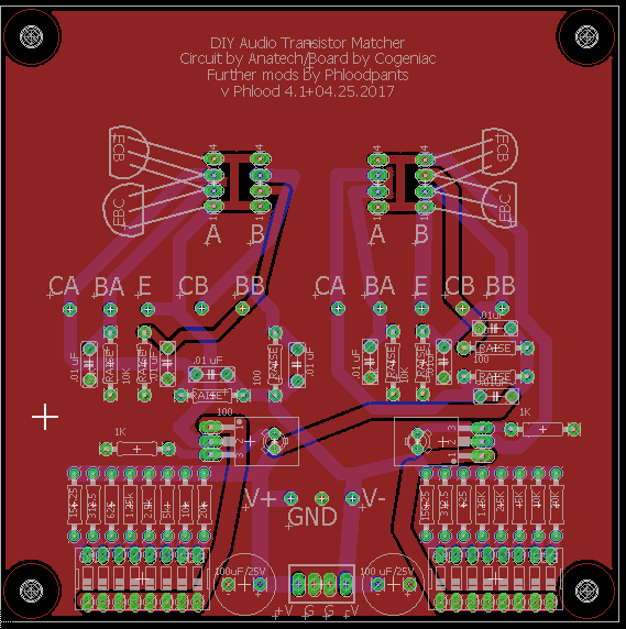
I seem to be making a lot of mods to the Eagle design. Besides the DIP-8 switches, I've added a few little features, like test points for V+ and V-, which gives a convenient spot to measure across the collector resistors. I've widened some traces so they'll hold up better to desoldering/resoldering. I moved some test points to more intuitive locations. Etc etc... Here's a screenshot of what I have so far...
Chris, what would I be looking for on the analyzer? (I don't have one, but I will probably put together a computer-based FFT soon) Just drift over time or would an FFT show something? If it's just drift over time, I have a Fluke 287 that does logging and graphing.
Last edited:
Hi Phloodpants,
The analyser would show you frequency peaks. All you are going for is a display similar to a spectrum analyser where frequency is plotted on the Y axis and amplitude is the X axis. It will show you harmonics, line noise and any non-harmonic peaks. After you reduce the amplitude of the input frequency, the "spectrum analyser" can then work at lower levels. This should allow you to see things from -90 dB to -110 dB. THis depends on the noise floor of the 8903B of course. You only take out the fundamental partially so you have something to lock onto. Then you can figure out what your actual levels are by looking at the level change on your fundamental and correcting for the drop. I always like to see what I'm measuring.
-Chris
Edit: Nice job on the board. I see you moved the power connections to the bottom of the board.
We're talking about the 565 control board again, yes? I'm not sure why I would need to see the FFT of the matcher board...?
But I do want a way to measure the noise output of amplifiers and such, with an FFT or just RMS AC levels. This noise is typically below 1mV, and too low to get useful readings on the 8903, or the Fluke, so I'm working on creating a super-low-noise "black box" amplifier with 40db of gain for this purpose. That should nicely elevate the noise above the noise!
Something like this at TNT audio, but I am using an AD797.
Simple Voltage Regulators Part 1: Noise - [English]
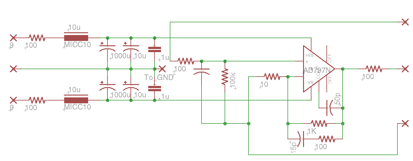
There will be pin-sockets for the gain resistors, as well as comp caps, so it can be re-configured for whatever purpose. The power supply is two 9V alkaline batteries (Very quiet) that go through a 10uH/100R/1000uF LCR filter. I figure that should be about as low noise as one can get. The AD797 has somewhere around 120db of PSRR, so this is probably a bit silly.
This will all be mounted in a small black aluminum box, with BNC and RCA connectors for in/out.
I don't have much experience designing ultra-low-noise op-amp circuits, so any criticism is welcome.
But I do want a way to measure the noise output of amplifiers and such, with an FFT or just RMS AC levels. This noise is typically below 1mV, and too low to get useful readings on the 8903, or the Fluke, so I'm working on creating a super-low-noise "black box" amplifier with 40db of gain for this purpose. That should nicely elevate the noise above the noise!
Something like this at TNT audio, but I am using an AD797.
Simple Voltage Regulators Part 1: Noise - [English]
An externally hosted image should be here but it was not working when we last tested it.
There will be pin-sockets for the gain resistors, as well as comp caps, so it can be re-configured for whatever purpose. The power supply is two 9V alkaline batteries (Very quiet) that go through a 10uH/100R/1000uF LCR filter. I figure that should be about as low noise as one can get. The AD797 has somewhere around 120db of PSRR, so this is probably a bit silly.
This will all be mounted in a small black aluminum box, with BNC and RCA connectors for in/out.
I don't have much experience designing ultra-low-noise op-amp circuits, so any criticism is welcome.
Last edited:
- Home
- Design & Build
- Equipment & Tools
- Matching transistors & measuring the results