That matches beta only. If you need to match Vbe only, or if you need to match both Vbe and beta, you need a different test fixture.
People who have studied an Algorithms textbook will recognize this as a problem with O(N^2) computational complexity. If you have 6 transistors A,B,C,D,E,F you have no choice but to test all (6^2 - 6)/2 possible pairings:
AB, AC, AD, AE, AF, BC, BD, BE, BF, CD, CE, CF, DE, DF, EF.
Thinking here, that is kind of like what my kid did this afternoon with dominos.
We were trying to identify which domino was missing, so she started lining them up at 4, then went up and down, etc.
60,..--,..--,..,--,..--.,..--, 66
50, 51, 52,..--,..--., 55,.--
40, 41, 42, 43, 44, 45, 46
30, 31, 32, 33,..--., 35, 36
20, 21, 22,..--,..--.,..--.,.26
10, 11,..--,..--,..--.,..--.,.16
00
I think I did that correctly, then when I asked her which domino
was missing she looked at it and identified that it was the 56.
Not bad for a 6 year old. 28 dominos 7 * 4...but not sure of the
equation now.
That matches beta only. If you need to match Vbe only, or if you need to match both Vbe and beta, you need a different test fixture.
People who have studied an Algorithms textbook will recognize this as a problem with O(N^2) computational complexity. If you have 6 transistors A,B,C,D,E,F you have no choice but to test all (6^2 - 6)/2 possible pairings:
AB, AC, AD, AE, AF, BC, BD, BE, BF, CD, CE, CF, DE, DF, EF.
Its actually an interesting problem - or rather group of problems. It depends a lot on your criterion - if you only want pairs to match within a specified tolerance you can pre-screen devices for Vbe, and also for gain, O(N). Depending on the statistics of the population that might help reduce the complexity.
To group things in multiple dimensions better than O(N^D) - where D is the number of dimensions - you can use quadtrees/octrees or their generalization, which encodes the notion of locality directly into the datastructure. Say you had 100000 transistors to pair up, this would make it tractable.
Of course in the real world if you have a large number of devices, you simply bin them for one property and then match only within the bins for the other. For 100000 devices you could use 300 Vbe bins and match for gain per-bin.
Search term "cluster analysis"....
Ok, so measuring across the collector resistors i'm able to set the test current at 3.35ma (335mv / 100ohm resistor)using the dip switches, this is the correct way to set the test current I take it?
When measuring across the collectors the voltage does not seem to settle, any pointers to where i'm going wrong?
When measuring across the collectors the voltage does not seem to settle, any pointers to where i'm going wrong?
The current is mirrored and split across the two collector resistors. It will drift around some; one will rise as the other falls. Instead, measure across the two collectors, and set the current source for double your target current. Then you should get a stable reading. Also you need a nice and stable power supply.
The test current should be set to whatever it is in your actual application. Higher currents will stabilize faster.
The test current should be set to whatever it is in your actual application. Higher currents will stabilize faster.
The current is mirrored and split across the two collector resistors. It will drift around some; one will rise as the other falls. Instead, measure across the two collectors, and set the current source for double your target current. Then you should get a stable reading. Also you need a nice and stable power supply.
The test current should be set to whatever it is in your actual application. Higher currents will stabilize faster.
Thanks for the reply,
Where you say measure across the two collectors, how am I doing this? When transistors are in the sockets its measuring them and when the sockets are empty theres no voltage.
Wait, sorry, I am confusing things. The only place where you could measure the shared current is across the current selection resistors, and you'd have to re-calculate that every time you change the dip switches. You could put a current meter in series with the current source, but there is no provision for that on the board.
What I do is just measure across one of the collector resistors, and check that the other one is in the same range. Average them roughly. It doesn't need to be super precise. Matched transistors will match over a fairly wide current range anyway.
What I do is just measure across one of the collector resistors, and check that the other one is in the same range. Average them roughly. It doesn't need to be super precise. Matched transistors will match over a fairly wide current range anyway.
Last edited:
So set across collector resistors for ~600mv so 6ma which is what Phloodpants advised double my target current of 3ma, if i've done my sums correctly. Now measuring across the transistor collectors am I looking for a steady reading (something i'm not getting) or is it best to use the average function on my meter?
Thanks
Thanks
Last edited by a moderator:
Yeah the reading will wander some. If you're looking for 3ma across each transistor, you should read approximately 300mV across each of the two collector resistors. You might have one that's 290mV, and another that's 310mV, as long as the total is about 600mV.
Sorry for confusing things. The double current thing is just that the current source is providing double the current seen by each transistor. Their sums will be steady, even as the two transistors wander around.
Sorry for confusing things. The double current thing is just that the current source is providing double the current seen by each transistor. Their sums will be steady, even as the two transistors wander around.
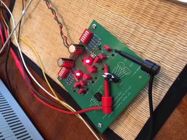
So with the current set at 2ma this is what a hfe sorted pair of ztx795a has come up with using the average function on my meter, its been pretty steady so far but did take its time to settle. I take it this is a good result?
 2020-06-26_03-48-14 by chris reddish, on Flickr
2020-06-26_03-48-14 by chris reddish, on FlickrHere are Gerbers and Eagle files for my latest fork of the Anatech/Cogeniac matching board. Feel free to share and order boards. I suggest JLCPCB.
Dropbox - DIYAudioTransistorMatcher EAGLE 2020.09.30.zip - Simplify your life
Dropbox - DIYAudioTransistorMatcher GERBERS 2020.09.30.zip - Simplify your life
Dropbox - DIYAudioTransistorMatcher EAGLE 2020.09.30.zip - Simplify your life
Dropbox - DIYAudioTransistorMatcher GERBERS 2020.09.30.zip - Simplify your life
OK folks!
I built up version II of the Beta matcher. It works very nicely!
Here are the Gerber and drill files.
http://www.mv-makoto.com/adcom/Matcher.zip
Here is a photo of my unit in operation,
...here are some PDFs of the schematic and board,
http://www.mv-makoto.com/adcom/MATCHER-SCH.pdf
http://www.mv-makoto.com/adcom/MATCHER-BRD.pdf
...and here are the raw Eagle files.
http://www.mv-makoto.com/adcom/Matcher-Eagle.zip
Have fun!
Scott
Edit: split from this thread:Yet Another Adcom GFA-565 Thread
I'm new to this transistor matching so I was wondering if there is more info available on the workings and how to use this Beta II tester.
I designed my own transistor matcher.
Just a simple inverting stage.
I use a microcontroller to send out a slowly rising ramp waveform to the base/gate.
It then reads in data from collector/drain into an array of data.
This array is then sent to a pc via USB bus.
The pc then plots up to 5 different waveforms for comparison.
You can zoom in and read off vce, hfe, Vb etc off the screen using pointers along the waveform.
Hi Nigel,
The critical aspect is that the pair must be at the same temperature when the readings are taken. By using a meter as a null tester, calibration (except for zero) is now mostly unimportant. Matches can be extremely tight. You don't really care what the beta actually is except for a rough idea. To measure beta, you do have access to the base current and collector current. Knowing collector current you can also get an approximate of the total tail current and if matched, divide that by two. So you can figure out what the actual beta is for that tail current and temperature.
Hi Tailgunner,
They all work the same. I designed the original circuit years ago and I am really happy that Cogeniac (and others) designed boards for these and made them available to you all. I think that Cogeniac has done a great service for everyone here.
It takes time for the pair to settle in to be the same temperature. Sorry, thermal equilibrium takes some time to achieve. Place the pair touching together in the jig. Cover the pair with close fitting foam, and cover the entire thing with a box or tin. I have found that a tail current of about 3 mA seems to work the fastest without overheating the parts. Your supply voltage should be very approximately 11 VDC. 9V will work fine, so will 15 V. Much higher will tend to cause things to get warmer.
Its too bad it takes a little time, and I hate matching transistors, but the result is measurably lower distortion and closer DC offset to what the circuit is designed to have. The diff pair is the critical spot in your amplifier.
As for complimentary pairs. I haven't taken the time to figure that out since the transistors are not going to match . What I do is match the various pairs, then measure the beta in the normal way taking care not to touch the transistors. Just take the closest complimentary pairs in beta. It isn't as perfect as the matches on your NPN or PNP pairs, but it is far better than doing nothing to match them.
Also, pre-match your groups using the normal beta tester, but try to keep them the same temperature. Makes going for the matches faster. Since I buy 50 or 100 transistors at a time, matching takes me a couple days on average. But, then I have a bunch of pairs. No, sorry. I don't sell them, they are used in my repairs and in prototypes. Remember, I hate matching transistors! I don't want to be a matching factory.
-Chris
Hey Chris!
I was thinking the same thing. Can't really expect N and P type devices to ever match that well. So, match the n pairs and p pairs and then try to match the betas of the pairs.
Chris Hoppe' page showed a set of 1000 transistors. I can't imagine matching those. One of the slowest and most boring tasks ever!
S
I designed my own transistor matcher.
Just a simple inverting stage.
I use a microcontroller to send out a slowly rising ramp waveform to the base/gate.
It then reads in data from collector/drain into an array of data.
This array is then sent to a pc via USB bus.
The pc then plots up to 5 different waveforms for comparison.
You can zoom in and read off vce, hfe, Vb etc off the screen using pointers along the waveform.
Yeah, what's really needed is a big array for. say 100 devices. Put it in an oven to temp set everything, and then measure all the devices at once. Store the data and then compute the best matches.
Lots of work unless you are in the business.
S
- Home
- Design & Build
- Equipment & Tools
- Matching transistors & measuring the results