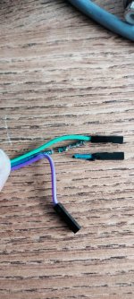
Don't ask me how or why Jan, these are the jumper wires for the silent switcher to the main board (15v rails)
Thought if check everything and for some reason it's like the cables had melted and become brittle? So much so that some of the wires were barely attached?

Thought if check everything and for some reason it's like the cables had melted and become brittle? So much so that some of the wires were barely attached?
Attachments

Hello Jan!
So, I have a problem with the Autoranger. I finally received the last item i needed to finish it, and I fired up to test it. I did not notice at the beginning, but this is how it looks upon boot:

Notice that even with no signal applied to the input, it starts off with -42dB attenuation and 156 or so Vin!!!

So, something's not right. I then set my Rigol function generator to 2.835,4Vpp so that it would give me about 1vrms on the 34401A.
I then applied that to the input of the AR, and... nothing happened. Well, since it is set automatically at boot for -42dB, I got 0.008,532 mVAC. But no autoswitch or anything.
So I set the AR on hold and cycled the attenuators from 0 to -36, and I got the following: 1.0001 VAC, 0.4996 VAC, 0.2487 VAC, 0.1244 VAC, 0.064178 VAC,
0.032138 VAC, 0.016239 VAC. The attenuators and relays work as intended, I believe. However, the information on the screen is also weird; i.e, at -36dB I see Vo1.24 and Vi 39.2... just to see if everything works ok, I also scaled down the Rigol's output to 0.2835 Vpp and tested the +dB range, getting the expected 0.20022 VAC, 0.39950 VAC etc, so the opamps also work well.
SO, I imagine the problem could be the LTC1968? problem with that would be that I had a HUGE problem finding one, and now I don't know what to do.
So, I have a problem with the Autoranger. I finally received the last item i needed to finish it, and I fired up to test it. I did not notice at the beginning, but this is how it looks upon boot:
Notice that even with no signal applied to the input, it starts off with -42dB attenuation and 156 or so Vin!!!
So, something's not right. I then set my Rigol function generator to 2.835,4Vpp so that it would give me about 1vrms on the 34401A.
I then applied that to the input of the AR, and... nothing happened. Well, since it is set automatically at boot for -42dB, I got 0.008,532 mVAC. But no autoswitch or anything.
So I set the AR on hold and cycled the attenuators from 0 to -36, and I got the following: 1.0001 VAC, 0.4996 VAC, 0.2487 VAC, 0.1244 VAC, 0.064178 VAC,
0.032138 VAC, 0.016239 VAC. The attenuators and relays work as intended, I believe. However, the information on the screen is also weird; i.e, at -36dB I see Vo1.24 and Vi 39.2... just to see if everything works ok, I also scaled down the Rigol's output to 0.2835 Vpp and tested the +dB range, getting the expected 0.20022 VAC, 0.39950 VAC etc, so the opamps also work well.
SO, I imagine the problem could be the LTC1968? problem with that would be that I had a HUGE problem finding one, and now I don't know what to do.
Your tests show that indeed the basic stuff is working and that it most probably is the LTC1968 which converts the ac signal to a DC potential to the controller.
It could also be the flat cable though.
What I can suggest to test is set the unit to 0dB manually, insert 1Vrms and verify that you have 1V at the output (all single ended).
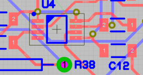
At that point check the ac going into the LTC1968 and the DC coming out as shown on the attachment.
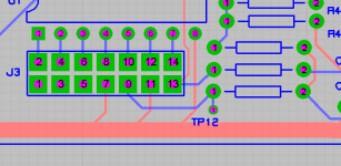
Ac input should be at pin 2, DC output at pin 5. Verify also the final DC output at TP12.
Jan
It could also be the flat cable though.
What I can suggest to test is set the unit to 0dB manually, insert 1Vrms and verify that you have 1V at the output (all single ended).
At that point check the ac going into the LTC1968 and the DC coming out as shown on the attachment.
Ac input should be at pin 2, DC output at pin 5. Verify also the final DC output at TP12.
Jan
Attachments
Last edited:
Hello Jan,
OK so here's what I have.
1.00212Vrms at the ARB output - and AR input. 1.00118 at the AR output, all set as you suggested.
Pin 2 is connected to one side of C11, so i measured the AC there. What I have is 0.1785 Vrms using the input BNC as gnd.
Pin 5, measured at the via next to it, is 0.1565 VDC.
Final output at TP12 is 0.790 VDC.
Edited to replace a mistyped comma with a point.
Ahh, well, all are soldered, and there are no visible shorts using a magnifying glass, however I cannot see under the IC, so could be.
Using a DMM at each pin in respect to GND, I get various resistance readings except obviously for pins 8 and 1, and the NC pin 4.
But pin 6 seems to be shorted to GND, I get 0.00006 Ohm, but I dont know if it is an expected behaviour
Using a DMM at each pin in respect to GND, I get various resistance readings except obviously for pins 8 and 1, and the NC pin 4.
But pin 6 seems to be shorted to GND, I get 0.00006 Ohm, but I dont know if it is an expected behaviour
Your tests show that indeed the basic stuff is working and that it most probably is the LTC1968 which converts the ac signal to a DC potential to the controller.
It could also be the flat cable though.
What I can suggest to test is set the unit to 0dB manually, insert 1Vrms and verify that you have 1V at the output (all single ended).
At that point check the ac going into the LTC1968 and the DC coming out as shown on the attachment.
Ac input should be at pin 2, DC output at pin 5. Verify also the final DC output at TP12.
Jan
Mine had a faulty Ltc1968 from new, faulty batch maybe? Works fine now it's been replaced.
Yes pin 6 is grounded. Sorry I've been away. I look into again.Ahh, well, all are soldered, and there are no visible shorts using a magnifying glass, however I cannot see under the IC, so could be.
Using a DMM at each pin in respect to GND, I get various resistance readings except obviously for pins 8 and 1, and the NC pin 4.
But pin 6 seems to be shorted to GND, I get 0.00006 Ohm, but I dont know if it is an expected behaviour
Jan
Hello Jan,Yes pin 6 is grounded. Sorry I've been away. I look into again.
Jan
sorry I have too returned from a work travel. So, I have at pin 7, U3 an AC voltage of 1.1543V.
I also tested the ribbon cable, there are no interruptions - however, if there is a voltage output at TP12, there should be a reading from the display, even if wrong; the display instead at power up shows 156V... it makes no sense. Unless the cable is not built correctly? I also re-tested the above measurements and i confirm them to the 5th digit.
I am at a loss....

...mind sharing (in PM eventually) where you sourced a replacement?Mine had a faulty Ltc1968 from new, faulty batch maybe? Works fine now it's been replaced.
I'd appreciate it...
...mind sharing (in PM eventually) where you sourced a replacement?
I'd appreciate it...
I do have a spare I think, I'll have to check. Where in the world are you?
I'm in Italy, Rome - zip code is 00145I do have a spare I think, I'll have to check. Where in the world are you?
You are correct that the DC at TP12 is the value that will be displayed, but it is modified by the attenuation that the controller think is in force.Hello Jan,
sorry I have too returned from a work travel. So, I have at pin 7, U3 an AC voltage of 1.1543V.
I also tested the ribbon cable, there are no interruptions - however, if there is a voltage output at TP12, there should be a reading from the display, even if wrong; the display instead at power up shows 156V... it makes no sense. Unless the cable is not built correctly? I also re-tested the above measurements and i confirm them to the 5th digit.
I am at a loss....
If you do the test with the attenuation manually set to 0dB it should be the same.
I'll look into it today.
Jan
@Pizzigri, to be sure we have a known starting point after the replacement, can you please recheck this:
What I can suggest to test is set the unit to 0dB manually, insert 1Vrms and verify that you have 1V at the output (all single ended).
At that point check the ac going into the LTC1968 and the DC coming out as shown on the attachment.
Ac input should be at pin 2, DC output at pin 5. Verify also the final DC output at TP12.
Jan
Hello Jan,@Pizzigri, to be sure we have a known starting point after the replacement, can you please recheck this:
What I can suggest to test is set the unit to 0dB manually, insert 1Vrms and verify that you have 1V at the output (all single ended).
At that point check the ac going into the LTC1968 and the DC coming out as shown on the attachment.
Ac input should be at pin 2, DC output at pin 5. Verify also the final DC output at TP12.
Jan
maybe I can obtain a LTC replacement, I will know this weekend.
However I imagine from this reply that you Strongly suggest the problem is only in the RMS converter? I am double checking because as wrong as the output is from the ic, And it has to be replaced nevertheless, there indeed is an output, but the AR does not act on it- it starts as if 156v are present at the input, and not the whatever wrong voltage the ltc detects and passes to tp12.
i was under the impression that the control board and the PIC would react to the dc voltage at tp12- it apparently does not.
i am going to measure the test points above listed but at power up when the first thing the control board does is switch the attenuator network to -42dB.
So Jan this is what I have:
AR as it turns on, it thinks there are 156V in and activates automatically a -42dB atten. I left it in this state.
1.0010 Vrms at the ARB output - and AR input. 8.5200 mVAC at the AR output,
Pin 2 is connected to one side of C10 (sorry "C11" in the post above was a typo since the silkscreen on the PCB lists the C10 and C11 stacked - but the measure has been done correctly), so i measured the AC there. What I have is 0.127 VAC using the input BNC as gnd.
Pin 5, measured at the via next to it, is 0.1225 VDC.
Final output at TP12 is 0.6153 VDC.
- Home
- Design & Build
- Equipment & Tools
- Autoranger for soundcards